Permanent magnet motor

a permanent magnet, motor technology, applied in the direction of magnetic circuit rotating parts, magnetic circuit shape/form/construction, windings, etc., can solve the problems of high cogging torque and poor motor efficiency, long magnetic path, high magnetic resistance, etc., to reduce the cogging torque of the motor, increase the motor efficiency, and reduce the noise of the motor

Active Publication Date: 2019-07-02
JOHNSON ELECTRIC SA
View PDF13 Cites 0 Cited by
  • Summary
  • Abstract
  • Description
  • Claims
  • Application Information

AI Technical Summary

Benefits of technology

[0006]Thus, there is a desire for a motor with enhanced efficiency and reduced cogging torque.
[0024]In view of the foregoing, the shape of the inner and outer surfaces of the permanent magnets is modified such that uneven air gaps are formed between the permanent magnet poles of the rotor and the magnetic poles of the stator. This reduces the cogging torque of the motor, thus increasing the motor efficiency, and reducing the motor noise. In addition, the motor efficiency is increased by modifying the structure of the stator core to include the inner annular portion, the connecting arms, the outer annular portion, the teeth and tips. In the magnetic core, the height of the teeth is shortened, such that the magnetic path is shortened and hence the magnetic resistance is reduced. The improvement on the construction of the stator core effectively reduces the magnetic resistance of the stator core and, as a result, reduces the iron loss of the motor and increases the motor efficiency.

Problems solved by technology

The motor with this configuration has a high cogging torque and poor motor efficiency.
This results in a long magnetic path and hence a high magnetic resistance.
The magnetic flux passing through the stator core formed by the core laminations 100 generates a large amount of heat, thus causing a significant iron loss of the motor and hence a poor efficiency of the motor.

Method used


Image

  • Permanent magnet motor
  • Permanent magnet motor
  • Permanent magnet motor

Examples


Embodiment Construction

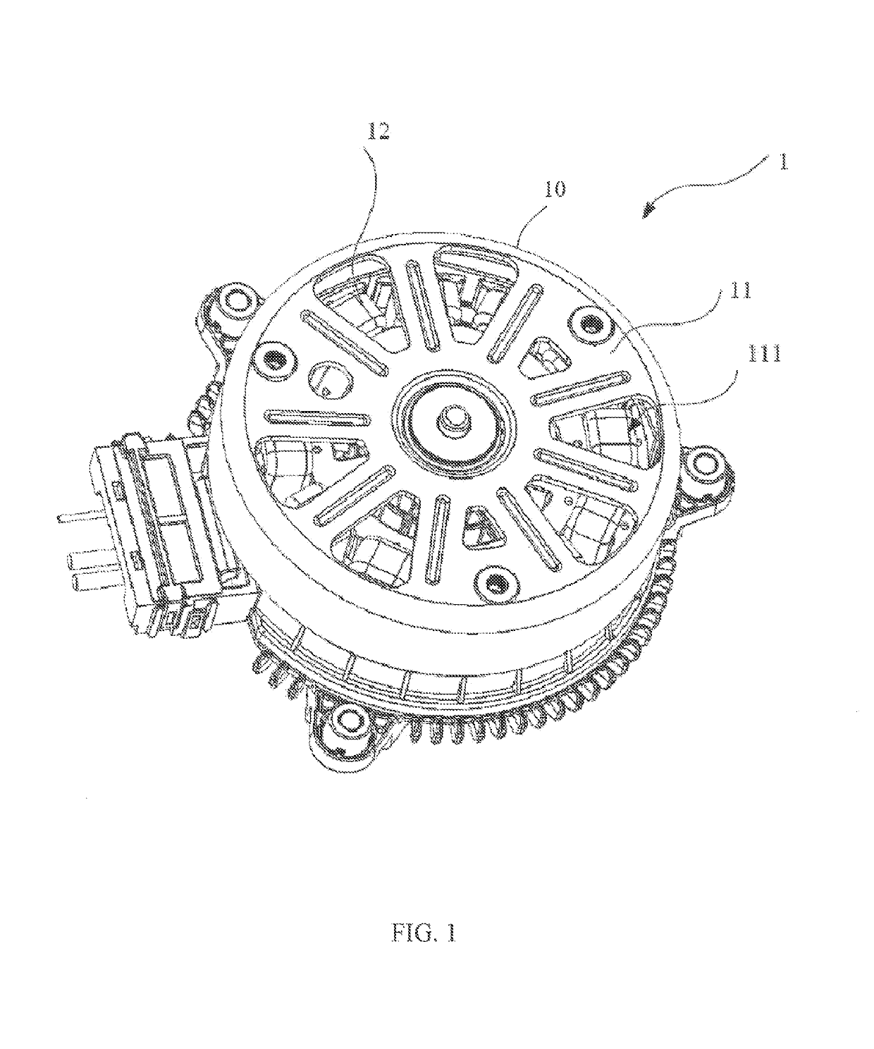
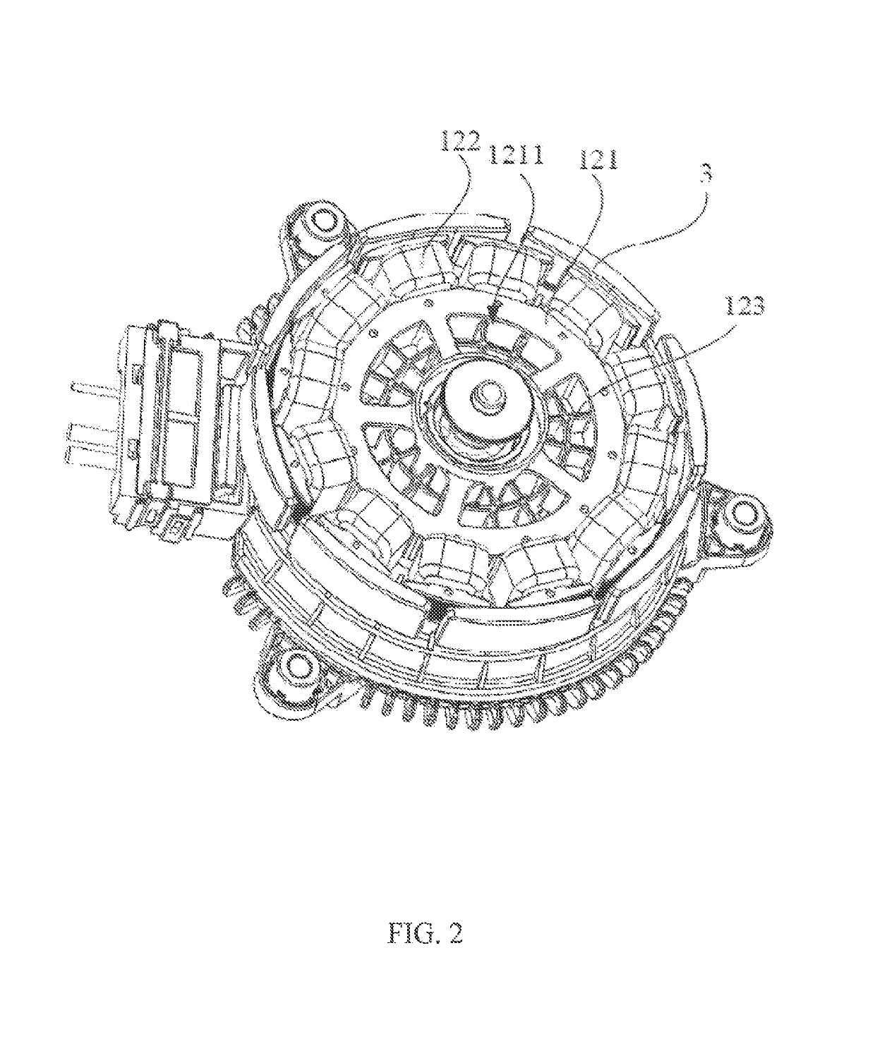
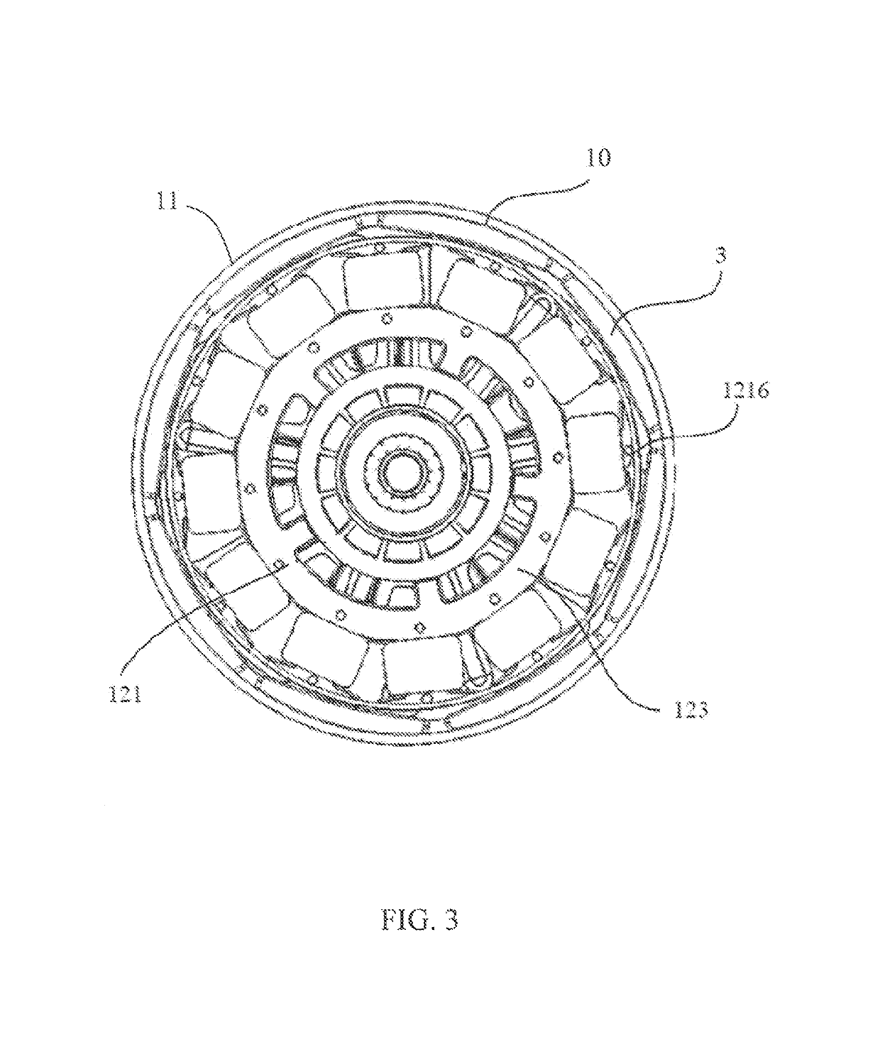
[0039]Referring to FIG. 1 through FIG. 3, a motor 1 in accordance with the preferred embodiment of the present invention includes a stator 12 and a rotor 10 rotatable relative to the stator. The rotor 10 includes an outer housing 11 and a plurality of permanent magnets 3 fixed to an inner surface of the outer housing 11 forming permanent magnet poles of the rotor. The stator 12 includes a stator core 121, stator windings 122 wound around the stator core 121, and a winding bracket 123 for insulating the stator core 121 from the stator windings 122. The winding bracket 123 is formed over an outer surface of the stator core 121 by an over-molding process, but exposes surfaces of tooth tips 1216 of the stator core 121 that confront the permanent magnet poles 3. The permanent magnet poles 3 are arranged surrounding an outer side of the stator core 121 and stator windings 122.

[0040]An end wall of the outer housing 11 of the rotor has a plurality of ventilation openings 111. Correspondingl...


PUM


Abstract

A permanent magnet motor has a number of permanent magnets forming permanent magnet poles. Each magnet has an outer surface that is an arc surface with a convex middle. An inner surface of the magnet is a curved surface with a concave middle. The curved surface has an arc surface section and two planar surface sections. The arc surface has a pole arc angle α of 0.7 to 0.96, and the ratio of an arc angle β of the arc surface section to the pole arc angle α is 0.15 to 0.35. The shape of the inner surface of the magnet creates uneven air gaps between the rotor poles and the stator core poles. This reduces cogging torque, increases the motor efficiency, and reduces the motor noise.

Description

CROSS REFERENCE TO RELATED APPLICATIONS[0001]This non-provisional patent application claims priority under 35 U.S.C. § 119(a) from Patent Application No. 201410235890.4 filed in The People's Republic of China on May 29, 2014, the entire contents of which are hereby incorporated by reference.FIELD OF THE INVENTION[0002]This invention relates to electric motors and in particular, to a permanent magnet motor having an uneven air gap between the rotor and stator.BACKGROUND OF THE INVENTION[0003]Electric motors have a stator and a rotor which is rotatable with respect to the stator. In an outer rotor motor the rotor is disposed around the stator. In a brushless DC motor the rotor has magnetic poles formed or created by one or more permanent magnets, while the stator has windings wound about the stator core to form the magnetic poles of the stator. The stator core is usually formed by a stack of core laminations of silicon steel to provide the magnetic flux path of the stator.[0004]The pe...

Claims


Application Information

Patent Timeline
Patent Type & Authority Patents(United States)
IPC IPC(8): H02K21/12H02K3/32H02K5/20H02K21/22H02K1/14H02K1/20H02K1/27
CPCH02K1/2786H02K1/146H02K1/20H02K5/20H02K21/222H02K3/325H02K2213/03H02K5/207H02K1/2791
Inventor JIANG, MAO XIONGZHAO, JIANSUN, GUO WEILI, YONGWANG, YONGZHAO, HONG JIANGLI, YUE
Owner JOHNSON ELECTRIC SA
Why Eureka
Try Eureka