
Reference signal transmission using multiple numerology

a reference signal and numerology technology, applied in the direction of digital transmission, transmission path division, transmission path sub-channel allocation, etc., can solve the problems of increasing implementation complexity, reducing the efficiency of resource utilization, and limiting the application of nr dmrs using various patterns

Active Publication Date: 2019-06-18
LG ELECTRONICS INC
View PDF4 Cites 5 Cited by
  • Summary
  • Abstract
  • Description
  • Claims
  • Application Information

AI Technical Summary

Benefits of technology

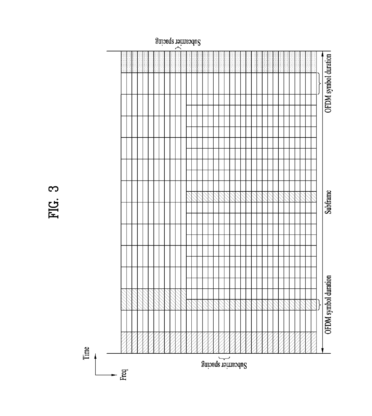
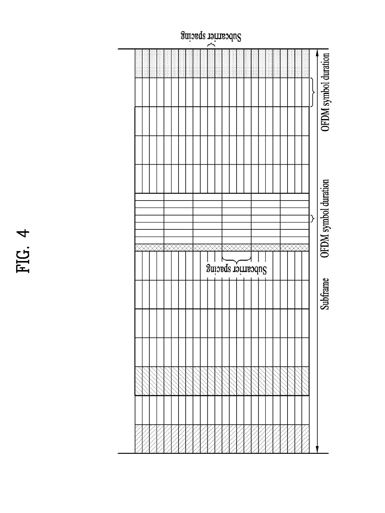
The present invention provides a method and apparatus for transmitting reference signals in a wireless communication system that can flexibly adapt to different system environments. The method involves acquiring a sequence for the reference signals and transmitting them through subframes consisting of a first type subframe and a second type subframe. The first type subframe includes a first number of OFDM symbols and the second type subframe includes a second number of OFDM symbols. The first and second positions of the OFDM symbols in the first and second type subframes are the same. The sequences can be generated based on the subframe with the smallest subcarrier spacing. The apparatus includes a processor and a transceiver for transmitting the reference signals at the same position in the first type subframe and the second type subframe. The first and second type subframes can be multiplexed with either a FDM or TDM scheme. The invention allows for more efficient use of reference signals and improved system performance.

Problems solved by technology

However, design of an NR DMRS using a single pattern on the assumption of an extreme environment may be considerably inefficient in terms of resource efficiency.
On the other hand, design of the NR DMRS using various patterns is problematic in that implementation complexity increases.

Method used


Image

  • Reference signal transmission using multiple numerology
  • Reference signal transmission using multiple numerology
  • Reference signal transmission using multiple numerology

Examples


Embodiment Construction

[0034]Reference will now be made in detail to the exemplary embodiments of the present invention, examples of which are illustrated in the accompanying drawings. The detailed description, which will be given below with reference to the accompanying drawings, is intended to explain exemplary embodiments of the present invention, rather than to show the only embodiments that can be implemented according to the present invention.

[0035]The following detailed description includes specific details in order to provide a thorough understanding of the present invention. However, it will be apparent to those skilled in the art that the present invention may be practiced without such specific details. In some instances, known structures and devices are omitted or are shown in block diagram form, focusing on important features of the structures and devices, so as not to obscure the concept of the present invention.

[0036]As described above, an aspect of the present invention provides a method of...


PUM


Abstract

A method and a device for transmitting reference signals in a wireless communication system are disclosed. For these, a sequence is acquired to be used for the reference signals, and the reference signals are transmitted through subframes comprising a first type subframe and a second type subframe. Here, the first type subframe includes a first number of OFDM symbols and the second type subframe includes a second number of OFDM symbols. And, a first position of OFDM symbol for transmitting the reference signals at the first type subframe is the same as a second position of OFDM symbol for transmitting the reference signals at the second type subframe.

Description

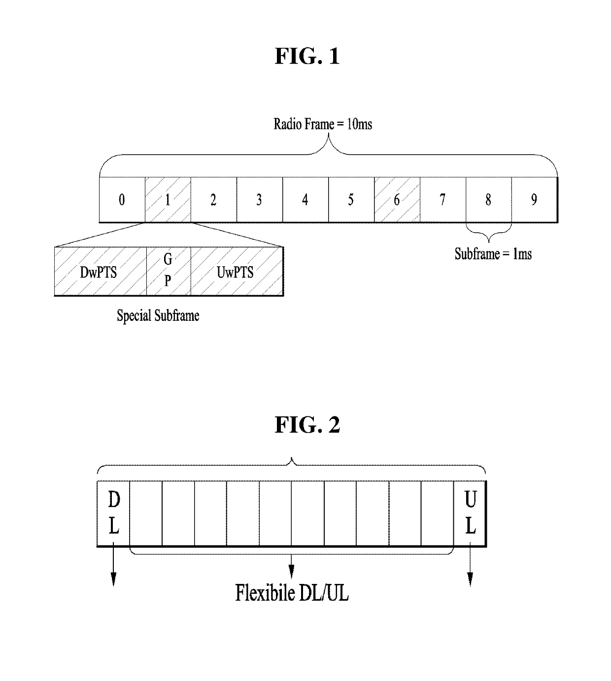
CROSS-REFERENCES[0001]This application claims the benefit of US Provisional Application No. 62 / 371,865, filed on Aug. 8, 2016, which is hereby incorporated by reference as if fully set forth herein.BACKGROUND OF THE INVENTIONField of the Invention[0002]The present invention relates to a method of transmitting and receiving a reference signal having a flexible structure according to a system environment in a wireless communication system and an apparatus therefor.Discussion of the Related Art[0003]Recently, standardization of mobile communication technology has reached studies on 5th Generation (5G) mobile communication via 4th Generation (4G) mobile communication technology such as LTE and LTE-A. In 3GPP, 5G mobile communication is referred to as New Radio (NR).[0004]It is apparent that design requirements of an NR system up to now are considerably diverse. For example, a used frequency band ranges from 700 MHz to 70 GHz, system bandwidth ranges from 5 MHz to 1 GHz, and mobile veloc...

Claims


Application Information

Patent Timeline
Patent Type & Authority Patents(United States)
IPC IPC(8): H04L5/00H04L5/26H04L1/16H04L5/10H04L1/00
CPCH04L5/0007H04L1/0083H04L1/1671H04L5/0048H04L5/0098H04L5/10H04L5/26
Inventor KO, HYUNSOOKIM, KIJUNKIM, EUNSUNYANG, SUCKCHEL
Owner LG ELECTRONICS INC
Learn More