
Tracking control systems for photovoltaic modules

a photovoltaic module and tracking control technology, applied in the direction of photovoltaic supports, heat collector mountings/supports, light and heating equipment, etc., can solve the problems of unfavorable widely-used photovoltaic power generation in under-developed areas, unfavorable placement, and significant increase in deployment costs and deployment difficulties, so as to reduce tracking costs and improve wind resistance of the entire photovoltaic tracking system. , the effect of best absorption of sunligh

Inactive Publication Date: 2019-06-18
ZHEJIANG TONKING NEW ENERGY GRP
View PDF32 Cites 5 Cited by
  • Summary
  • Abstract
  • Description
  • Claims
  • Application Information

AI Technical Summary

Benefits of technology

The present invention provides a single-axis and two-axis tracking system that tracks sunlight and wind to maximize photovoltaic module efficiency and power generation. The system uses one set of tracking control systems to control and track multiple photovoltaic modules, reducing tracking costs and improving wind resistance. The two-axis tracking system provides additional benefits of receiving sunlight in a most efficient manner and increased power generation efficiency. Both systems offer increased safety and durability.

Problems solved by technology

If it comes to a large-scale deployment on a large area, then it requires the number of controlling and driving systems equals to the number of the photovoltaic module subsystems, which substantially increases the deployment costs and deployment difficulties, and is unfavorable for the widely-spread utilization of photovoltaic power generation in under-developed areas.
However, such placement is not the most efficient scheme.
However, for some areas, due to reasons such as non-horizontal deploying terrains and cloud cover in the sky, even if the assembly is adjustable in the east-west direction, it is still unable to adjust the panel of the photovoltaic module subsystem to be perpendicular to the incident direction of maximal optic axis in case of fixing the assembly in the south-north direction.
This puts high requirements on the wind resistance of the assembly.
On the basis of the above requirements, in the field of photovoltaic power generation so far, there is a lack of a tracking system for photovoltaic module which provides tracking control for multiple assemblies of the photovoltaic modules in a centralized manner, can be deployed in large areas on various terrains, and has good wind resistance.

Method used

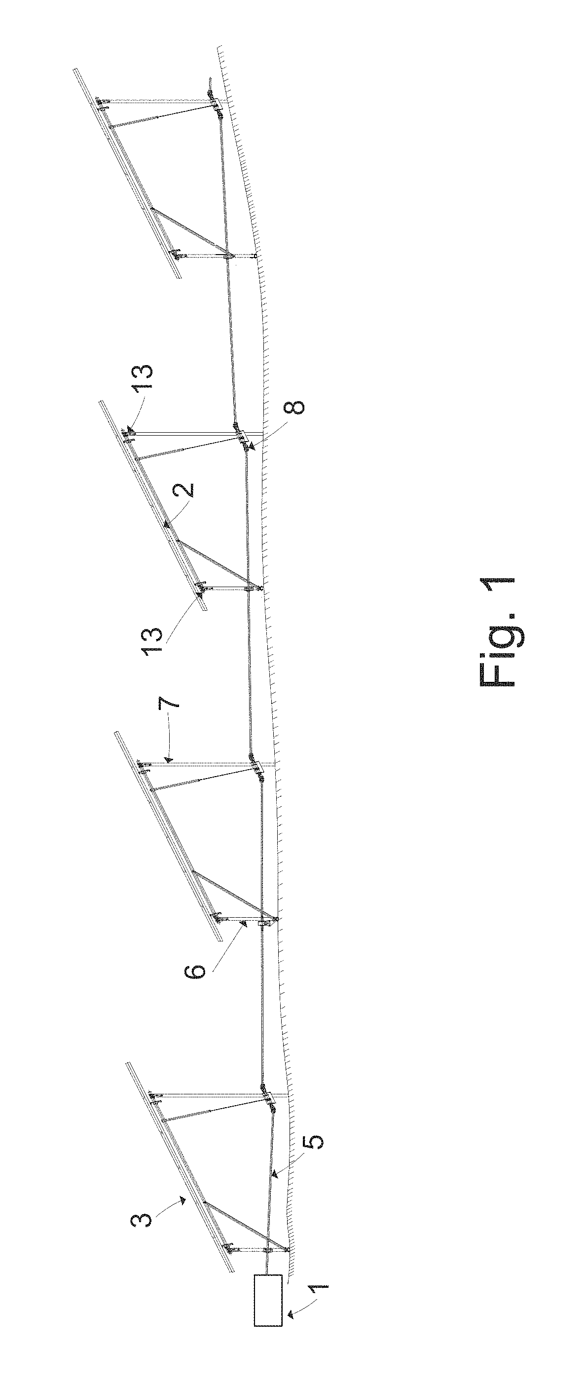
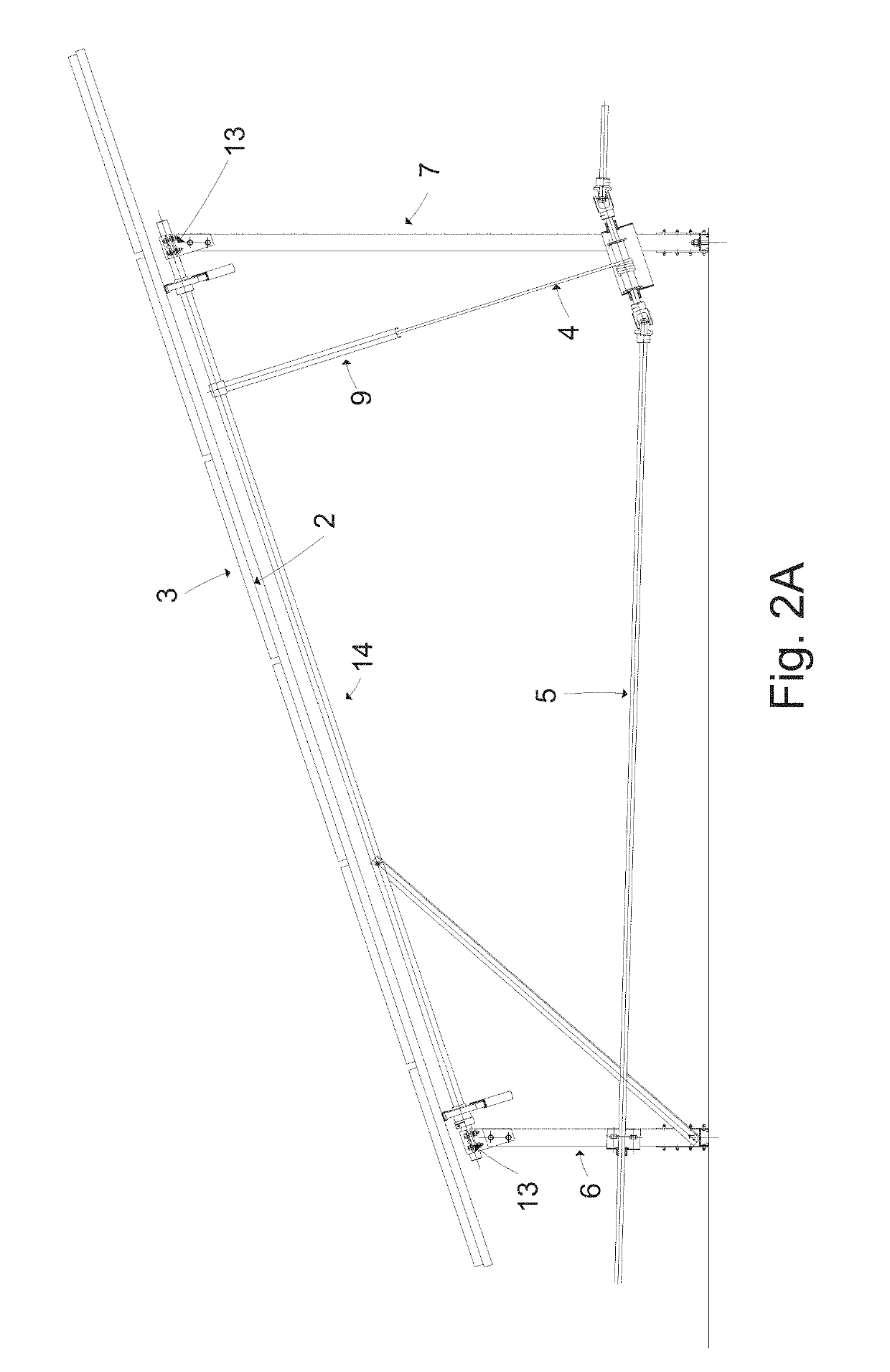
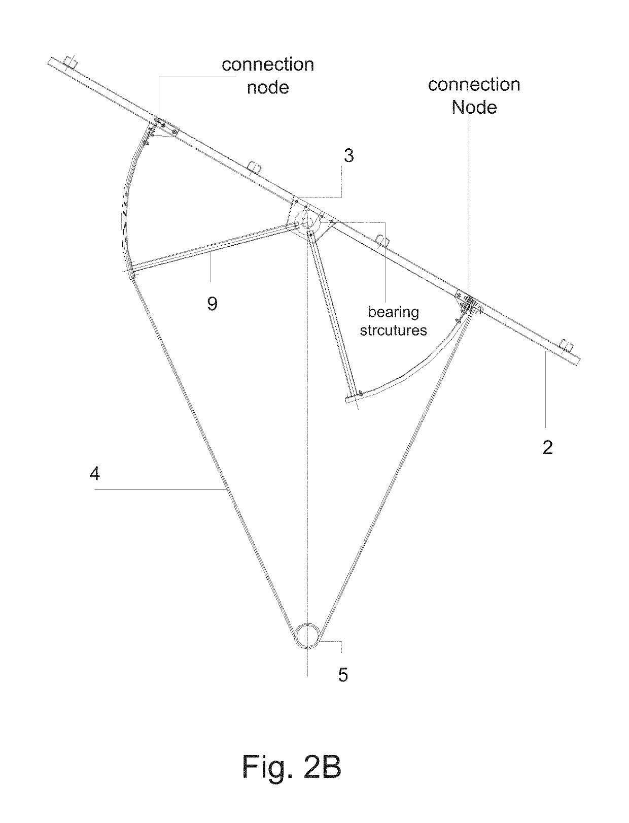

Image

  • Tracking control systems for photovoltaic modules
  • Tracking control systems for photovoltaic modules
  • Tracking control systems for photovoltaic modules

Examples


Embodiment Construction

[0034]With reference to the detailed non-limiting embodiments as illustrated in the drawings and elaborated below, the technical features and details are explained more completely. A description of generally known raw materials, processing techniques, components and devices is omitted in the following description, so as not to unnecessarily obscure the essential technical points of the present disclosure. However, as those skilled in the art will understand, when describing the embodiments of the present disclosure in the following, the description and specific examples are given in an illustrative but non-limiting manner.

[0035]Wherever possible, the same reference numerals will be used to represent the same or similar parts throughout the drawings. Furthermore, although the terms as used herein are selected from well-known terms, some terms mentioned in the specification of the present disclosure may be selected by the inventor according his / her own decisions, and the concrete mean...


PUM


Abstract

The object of the present disclosure lies at least in providing a multi-assembly tracking control system for solar photovoltaic module, which may control multiple sets of photovoltaic module assemblies simultaneously, so as to enable a single-axis tracking in one direction or a two-axis tracking in two directions. It is able to receive the sunlight in a most efficient manner under various climate and deployment conditions, to greatly raise the power generation efficiency and to enhance the stability of the whole system.

Description

CROSS REFERENCE TO RELATED APPLICATIONS[0001]The present specification claims priority to Chinese Patent Application No. CN 201420057701.4 filed Jan. 30, 2014 and to Chinese Patent Application No. CN 201410452129.6 filed Sep. 5, 2014, each or which are incorporated by reference herein in their entireties.BACKGROUND[0002]Field[0003]The present specification generally relates to the field of photovoltaic power generation and, in particular, to a tracking control system for photovoltaic power generation devices.[0004]Technical Background[0005]Solar photovoltaic power generation refers to a technology in which the incident sunlight is received by an array formed by solar photovoltaic module subsystems, converted into electric energy through photovoltaic conversion, and the generated electric energy is collected for use. This technology has the advantages of pollution-free, inexpensive and sustainable power generation, and it is increasingly applied in the tropical or desert regions arou...

Claims


Application Information

Patent Timeline
Patent Type & Authority Patents(United States)
IPC IPC(8): H02S20/32H02S20/10H02S20/30
CPCH02S20/32H02S20/10F24S30/455F24S30/428F24S25/13Y02E10/47F24S2030/133Y02E10/50
Inventor WU, JIAN NONG
Owner ZHEJIANG TONKING NEW ENERGY GRP
Learn More