Structural joint

a technology of structural joints and joints, applied in the direction of bridge structural details, ways, paving details, etc., can solve the problems of differences in height between plates, insufficient presence of such cogging interlocks, and insufficient presence of such load transfer elements to prevent damage at the upper circumferential edges of floor elements

Active Publication Date: 2019-06-18
HENGELHOEF CONCRETE JOINTS
View PDF86 Cites 9 Cited by
  • Summary
  • Abstract
  • Description
  • Claims
  • Application Information

AI Technical Summary

Benefits of technology

[0011]In creating the upper edges of the concrete slabs, the upper portion of the expansion joint according to the present invention may further comprises a second vertically oriented corrugated plate that fits within the undulations of the vertically oriented corrugated plate of the upper portion to protect the upper edge of the opposing slab. Analogously, in creating the lower edges of the concrete slabs, the lower portion of the expansion joint according to the present invention may further comprise a second vertically oriented corrugated plate that fits within the undulations of the vertically oriented corrugated plate of the lower portion to protect the lower edge of the opposing slab.

Problems solved by technology

However, when driving over such an expansion joint with heavily loaded vehicles such as forklifts, which often have particularly hard Vulkollan wheels, the presence of such load transfer elements cannot prevent damage of the upper circumferential edges of the slabs or to the wheels, due to the undesirable shock of the vehicle when passing the groove-like gap between the floor elements.
This is especially due to the fact that the joint profile making up the edges of the floor elements is made of steel and therefore much harder than the commonly soft outer circumference surface of the wheels.
However, in as far each of said arrangements ensures that the wheels when leaving one edge are already supported on the boundary of the other; the mere presence of such cogging interlocks is insufficient to prevent damage at the upper circumferential edges of the floor elements.
Vertical tilting of the floor members may still result in differences in height between the plates which gives rise to edges, further shocks and eventual damages to the floor.
In addition, metal interlocking end plates such as shown in AT113488 and JP-2-29603, still result in an abrupt change of expansion coefficient at the boundary of the floor slabs.
As a consequence, these end plates tend to loosen over time with floor damage at the boundary between the concrete floor slabs at the metal end plates.

Method used


Image

  • Structural joint
  • Structural joint
  • Structural joint

Examples


Embodiment Construction

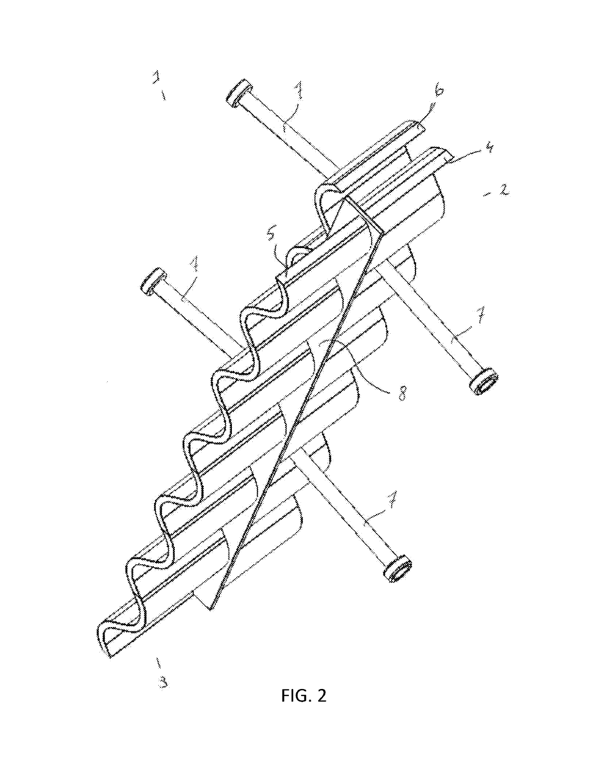
[0023]With reference to FIGS. 1 and 2, the expansion joint according to the present invention has an upper (2) and lower (3) portion each comprising a vertically oriented corrugated plate (4, 5), characterized in that the corrugated plates of the upper (4) and lower (5) portion are out of phase to one another.

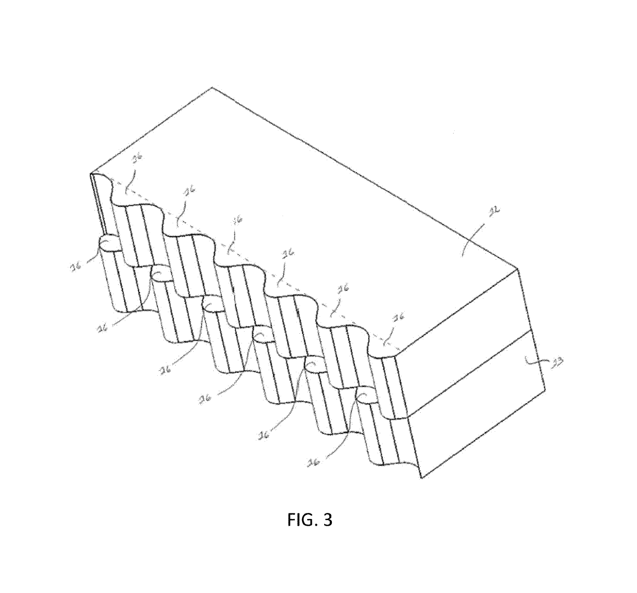
[0024]Within the context of the present invention there is no particular limitation as to the corrugation of the plates, in principle any alternating form is suitable, including wave, zigzag or dent forms. Where the amplitude and width of the corrugation between the upper and lower portion may be different, in one embodiment the corrugation of the upper and lower plates will be the same. In a particular embodiment the corrugation will consist of a waveform. In a more particular embodiment the corrugation of the upper and lower plate will be the same and consisting of a waveform.

[0025]The upper and lower corrugated plates (4, 5) will be in substantially the same lateral plane, b...


PUM


Abstract

The present invention relates to a expansion joint to bridge an expansion gap between two parts of concrete slabs used in floor construction, especially in the manufacture of concrete floors such as for example in industrial floors. Such expansion joints are evidently required to take up the inevitable shrinkage process of the concrete and to assure that the floor elements can expand or contract such as for example occur by temperature fluctuations and resulting in a horizontal displacement of the floor panels vis-à-vis one another.

Description

CROSS-REFERENCE TO RELATED APPLICATIONS[0001]This application is a continuation of U.S. patent application Ser. No. 14 / 380,803, filed Aug. 25, 2014, which is a U.S. National Stage Entry of International Patent Application No. PCT / EP2013 / 053849, filed on Feb. 27, 2013, which designated the United States and claims priority to Great Britain Patent Application 1203314.18, filed on Feb. 27, 2012, Great Britain Patent Application 1215277.3, filed on Aug. 28, 2012, and Great Britain Patent Application 1220095.2, filed on Nov. 8, 2012, the contents of which are hereby incorporated by reference in their entirety.FIELD OF THE INVENTION[0002]The present invention relates to a expansion joint to bridge an expansion gap between two parts of concrete slabs used in floor construction, especially in the manufacture of concrete floors such as for example in industrial floors. Such expansion joints are evidently required to take up the inevitable shrinkage process of the concrete and to assure that ...

Claims


Application Information

Patent Timeline
Patent Type & Authority Patents(United States)
IPC IPC(8): E01C11/02E01C11/14E01D19/06E01C11/08
CPCE01C11/08E01C11/14E01D19/06Y10T403/21E01C11/04
Inventor MEUWISSEN, DIRKKLINGELEERS, ALBERT CHARLESWINTERS, RENE ALICE P.
Owner HENGELHOEF CONCRETE JOINTS
Why Eureka
Try Eureka