Light guide, especially for signal lamps of motor vehicles
a technology for signal lamps and light guides, which is applied in the direction of mechanical equipment, lighting and heating equipment, instruments, etc., can solve the problems of reducing the efficiency of the output characteristic required by regulations, and affecting the efficiency of the output characteristi
- Summary
- Abstract
- Description
- Claims
- Application Information
AI Technical Summary
Benefits of technology
Problems solved by technology
Method used
Image
Examples
first embodiment
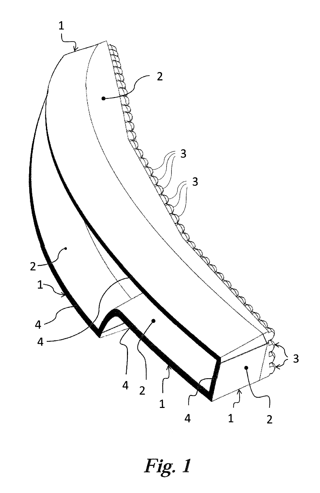
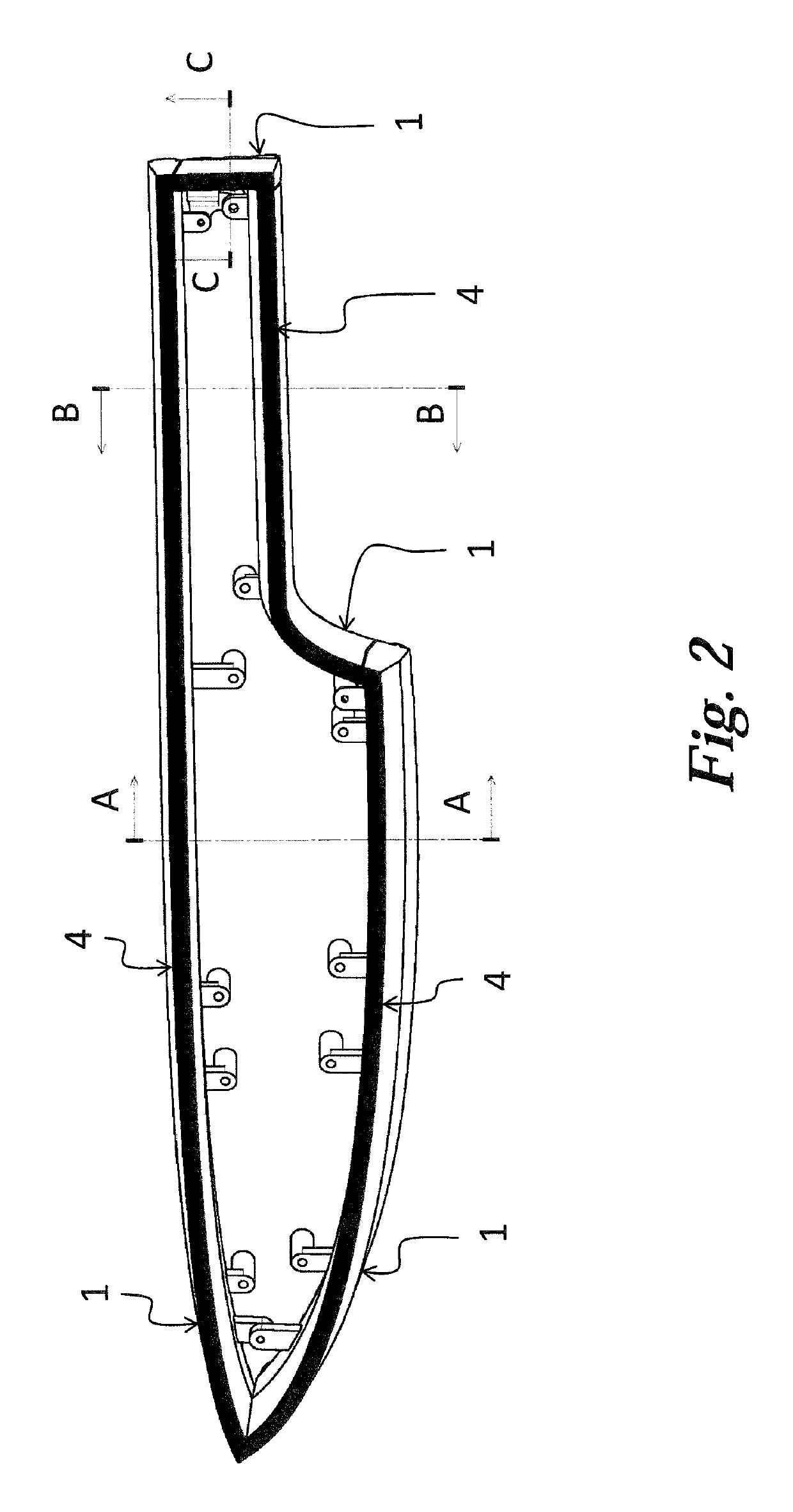
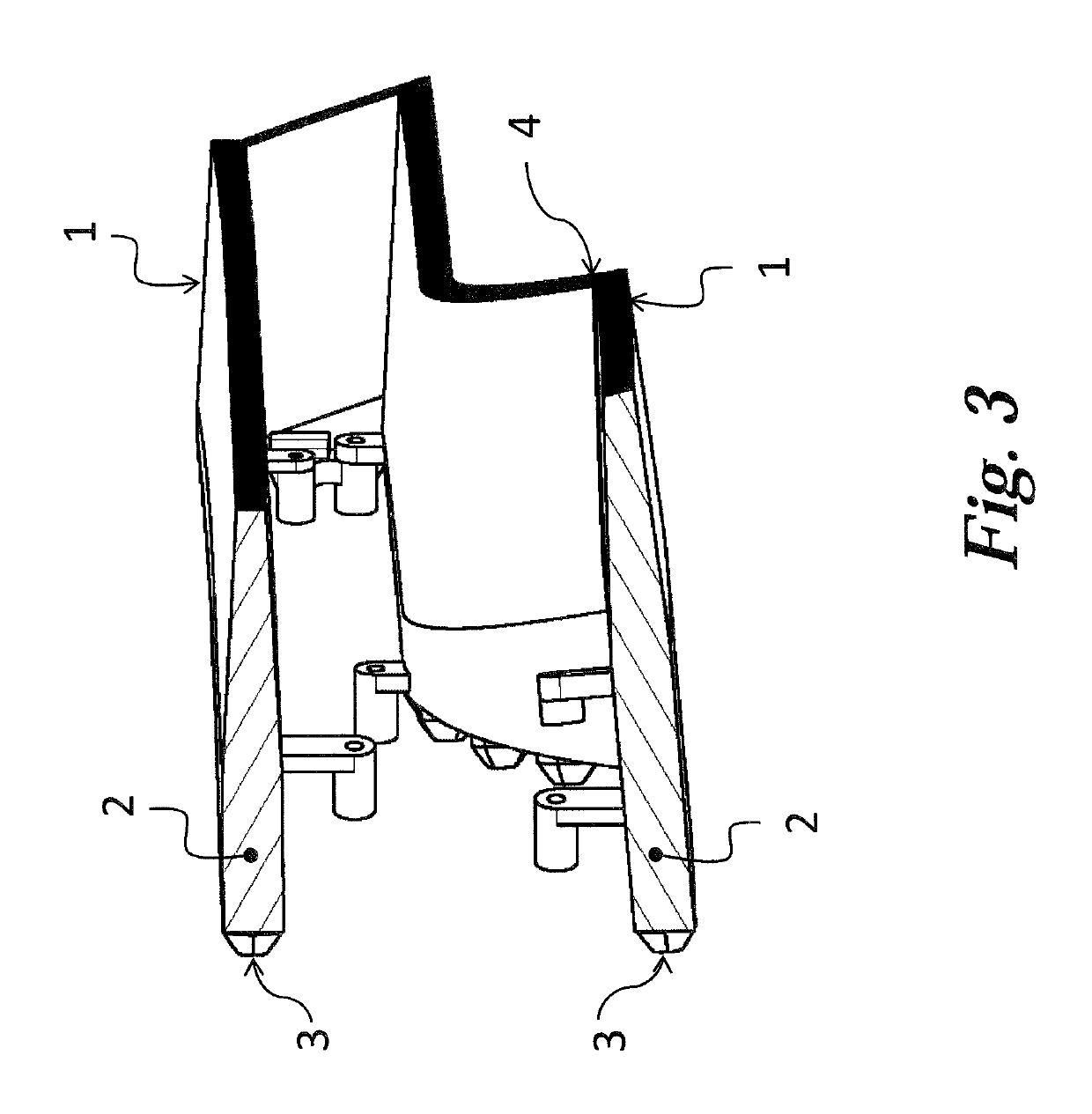
[0023]FIGS. 1, 2, 3 and 4 show the light guides in accordance with the invention in different views. The light device comprises four light guides implemented in the form of integral, spatially shaped planar elements 1. Each light guiding element 1 comprises a planarly shaped light guiding body 2 adapted to conduct light. The light guiding body 2 is designed as light conducting, and is fitted with collimators 3 at its entry part and with a continuous emitting surface 4 on its outer side. In addition, the light guiding body 2 gets narrower from the collimator 3 towards the emitting surface 4, i.e. the longitudinal profile gets smaller in the direction of the optical axis x. Each emitting surface 4 of the light device is adapted to provide a different light function, e.g. to emit the positional, brake, direction indicator or fog light, the emitting surfaces 4 creating a certain designer element.
[0024]FIG. 5 represents a detailed view of the first embodiment of the light guide, which is...
second embodiment
[0030]FIG. 6 shows the light guide, which comprises two transitional surfaces 22 with different inclination lengths b, b′ and different inclination heights a, a′. Either transitional surface 22 is subject to the above mentioned relationship between the inclination length b of this transitional plane 22 and the inclination height a of this inclination plane 22. The collimator 3 is designed as symmetrical, while between the collimator 3 and the shorter inclination length b′ a superstructural element 23 is situated.
third embodiment
[0031]FIG. 7 shows the light guide wherein the light guiding body 2 contains a superstructural segment 23 having the length e, which is situated between the collimator 3 and the transitional surfaces 22, its longitudinal profile being constant in the direction from the collimator 3 to the transitional surfaces 22 of the body 2. End light ray 101 generally delimits, in vertical direction, a boundary of an angle range within which rays 100 are emitted from the emitting surface 4. In another embodiment, the superstructural element may be beveled under a withdrawing angle to improve moldability, depending on the mold design, in the direction towards or from the collimator.
PUM
 Abstract
Description
Claims
Application Information
 - R&D
- Intellectual Property
- Life Sciences
- Materials
- Tech Scout
- Unparalleled Data Quality
- Higher Quality Content
- 60% Fewer Hallucinations
Browse by: Latest US Patents, China's latest patents, Technical Efficacy Thesaurus, Application Domain, Technology Topic, Popular Technical Reports.
© 2025 PatSnap. All rights reserved.Legal|Privacy policy|Modern Slavery Act Transparency Statement|Sitemap|About US| Contact US: help@patsnap.com


