Self-draining oil buoyancy regulating device for underwater robots

a robot and self-draining technology, applied in underwater equipment, positive displacement liquid engines, special-purpose vessels, etc., can solve the problems of hard energy supply, waste of energy, and inability to control the buoyancy by active propelling, and achieves low energy consumption, easy control, and quick switch

Active Publication Date: 2019-06-04
ZHEJIANG UNIV
View PDF6 Cites 3 Cited by
  • Summary
  • Abstract
  • Description
  • Claims
  • Application Information

AI Technical Summary

Benefits of technology

[0008]An object of the present invention is to provide a self-draining oil buoyancy regulating device for underwater robots, which is a buoyancy regulating solution has the advantages of stable, easy to control, quick switch between oil drainage and oil return, low energy consumption, compact structure, light weight and small volume. The present invention is applied in the buoyancy and depth control for underwater appliance.
[0019]1. By adopting a whole hydraulic plan, there are no other movement components except the pump and motor. All the key sealing parts are static seal, which makes the mechanical transmission has reliable sealing and has long service life.
[0020]2. Realize the active oil drainage and passive oil return by taking the advantage of the accumulator, which reduces the energy consumption and increases the energy efficiency. At the mean time the problem of the active oil return failure if the water is shallow and the external pressure is lower than the friction loss. Compared to the conventional hydraulic solution by adopting the present invention the working duration under the water is prolonged; the stability is improved; and the quick switch between the oil drainage and oil return is fulfilled. The accumulator is a standard component which is low in cost and easy to find.
[0021]3. By adopting the directional valve and the relief valve, the oil channel is simplified. By using the hydraulic-operated check valve and building a self-locking oil channel accordingly the leakage of the accumulator inside the oil channel is reduced without compromise the function, which enhances the security. The valve block assembly reduces the whole assembling volume of the oil channel and makes the appliance compact.

Problems solved by technology

The underwater environment makes the energy supply hard so control the buoyancy by active propelling is impossible, which makes the buoyancy regulating device necessary for the appliances to regulate the buoyancy and move up and down.
To overcome the static friction caused by maintaining the self-locking consumes energy, which wastes the energy and cause low efficiency.
Besides changing the relative position of the rigid bodies by piston makes the sealing underwater a difficult problem to solve compared to other methods and reduces the reliability.
The reciprocating motion of the piston inside the cylinder undermines the reliability due to the sealing problem.
The conventional hydraulic system has complex valve system which increases the weight and volume of the appliance.
The problem of the passive oil drainage and active oil return plan is when the water is shallow and the external pressure is lower than the friction loss the active oil return fails.
The problem of passive oil drainage and passive oil return is that a two-way pump is needed.
The hydraulic pump is on during the oil return and oil drainage, which consumes the energy.
The two-way pump is unable to quick switch between forward and reversal rotation, which affects the control performance.
The compression of high pressure gas is accomplished by water pump, which is hard to control due to the process of gas compression is nonlinear and tend to be affected by many factors.
The water pump is not reliable and has short service life if stay in the sea for a long time.
The phase change is a complex nonlinear thermodynamic process and the gas generated is easy to be compressed, which is hard to control.

Method used


Image

  • Self-draining oil buoyancy regulating device for underwater robots
  • Self-draining oil buoyancy regulating device for underwater robots
  • Self-draining oil buoyancy regulating device for underwater robots

Examples


Embodiment Construction

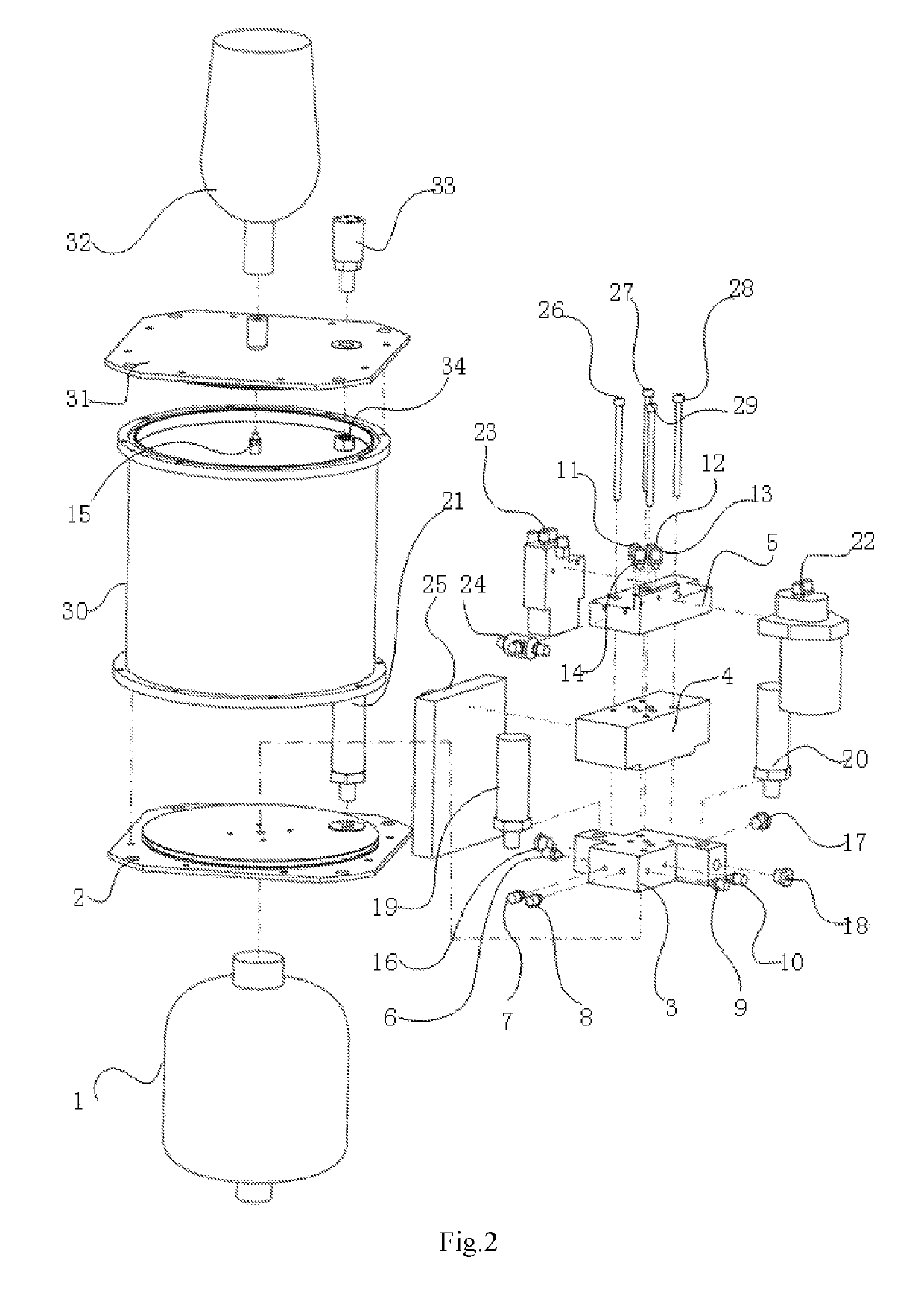
[0034]Referring to FIG. 1 to FIG. 11 of the drawings, according to a preferred embodiment of the present invention is illustrated, comprising: accumulator 1, lower hatch cover 2, lower valve block 3, hydraulic-operated check valve 4, upper valve block 5, 1st oil pipe connector 6, 2nd oil pipe connector 7, 3rd oil pipe connector 8, 4th oil pipe connector 9, 5th oil pipe connector 10, 6th oil pipe connector 11, 7th oil pipe connector 12, 8th oil pipe connector 13, 9th oil pipe connector 14, 10th oil pipe connector 15, 1st oil channel plug 16, 2nd oil channel plug 17, 3rd oil channel plug 18, pump outlet pressure sensor 19, accumulator pressure sensor 20, depth-pressure sensor 21, hydraulic pump motor assembly 22, directional valve 23, relief valve 24, control panel 25, 1st bolt 26, 2nd bolt 27, 3rd bolt 28, 4th bolt 29, hatch shell 30, upper hatch cover 31, bladder 32, water-proof connector 33, nut 34 and several oil pipes; wherein an overlay hydraulic-operated check valve 4 with a mo...


PUM


Abstract

The present invention provides a self-draining oil buoyancy regulating device for underwater robots, wherein the accumulator, lower hatch cover, hatch trunk, upper hatch cover and bladder are connected; the water-proof connector is fixed on the upper hatch cover; the depth-pressure sensor is settled on the lower hatch cover; the upper valve block, hydraulic-operated check valve and lower valve block are connected; the lower valve block is fixed on the lower hatch cover; the pump outlet pressure sensor and the accumulator pressure sensor are on the lower valve block; the directional valve and the upper valve block are connected; the hydraulic pump motor assembly and the relief valve are both connected with the lower valve block; the depth-pressure sensor, pump outlet pressure sensor and accumulator pressure sensor are all connected with the control panel; the control panel is connected with the external power supply and the host computer.

Description

CROSS REFERENCE OF RELATED APPLICATION[0001]This is a U.S. National Stage under 35 U.S.C 371 of the International Application PCT / CN2015 / 092177, filed Oct. 19, 2015.BACKGROUND OF THE PRESENT INVENTIONField of Invention[0002]The present invention relates to a buoyancy regulating device, and more particularly to a self-draining oil buoyancy regulating device for underwater robots.Description of Related Arts[0003]Underwater robots and other underwater appliances work in different depth under the water, which requires a control over the movement and depth in the water. The underwater environment makes the energy supply hard so control the buoyancy by active propelling is impossible, which makes the buoyancy regulating device necessary for the appliances to regulate the buoyancy and move up and down.[0004]The conventional methods for regulating the buoyancy are mechanical transmission, active oil pumping, load rejection, water drainage and phase change.[0005]Mechanical transmission metho...

Claims


Application Information

Patent Timeline
Patent Type & Authority Patents(United States)
IPC IPC(8): B63G8/24B63C11/52B63G8/22F04B49/06
CPCB63G8/24B63G8/22B63C11/52F04B49/065
Inventor KANG, CHANGLINZHOU, CHUNLINXIONG, RONGZHU, QIZHU, QIUGUOLIU, YONG
Owner ZHEJIANG UNIV
Why Eureka
Try Eureka