Torque transmission joint and electric power steering device

a transmission joint and torque technology, applied in the direction of electric steering, yielding couplings, vehicle components, etc., can solve the problems of backlash at the spline engagement portion, inability to suppress abnormal noise, and inability to adjust the spline flexural angle, etc., to improve the assembling property, suppress abnormal noise generation, and suppress abnormal noise generation

Active Publication Date: 2019-05-14
NSK LTD
View PDF32 Cites 10 Cited by
  • Summary
  • Abstract
  • Description
  • Claims
  • Application Information

AI Technical Summary

Benefits of technology

[0042]According to the torque transmission joint and the electric power steering device of the present invention, it is possible to suppress generation of the abnormal noise when changing the rotational direction of the driving shaft.
[0043]That is, according to the present invention, the axial portions of the driving-side concave-convex portion and the driven-side concave-convex portion are respectively engaged with the coupling-side concave-convex portion with the circumferential gap being interposed therebetween, and the axially remaining portions of the driving-side concave-convex portion and the driven-side concave-convex portion are respectively engaged with the coupling-side concave-convex portion with the driving-side elastic piece and the driven-side elastic piece being interposed therebetween, which configure the elastic member made of the elastic material such as elastomer, for example rubber. Therefore, according to the present invention, when torque to be transmitted between the driving shaft and the driven shaft is relatively low, the rotation torque of the driving shaft is transmitted to the driven shaft via the elastic member.
[0044]In contrast, when the torque to be transmitted between the driving shaft and the driven shaft increases, each driving-side elastic piece and each driven-side elastic piece are elastically deformed (elastically crushed) in the circumferential direction. The circumferential side surfaces of the convex portions configuring the axial portion of the driving-side concave-convex portion of the driving shaft and the circumferential side surfaces of the convex portion configuring the coupling-side concave-convex portion of the coupling directly collide (contact) each other, and the circumferential side surfaces of the convex portions configuring the coupling-side concave-convex portion and the circumferential side surfaces of the convex portions configuring the axial portion of the driven-side concave-convex portion of the driven shaft directly collide (contact) each other. Since the collision momentums are weakened by the elastic member, it is possible to suppress generation of the abnormal noise such as gear striking noise at the contact portion between the respective concave-convex portions, which is to be caused as the collision occurs. At this state, most of the rotation torque of the driving shaft is transmitted to the coupling by the engagement between the axial portion of the driving-side concave-convex portion and the coupling-side concave-convex portion, and most of the torque transmitted to the coupling is transmitted to the driven shaft by the engagement portion between the coupling-side concave-convex portion and the axial portion of the driven-side concave-convex portion. That is, according to the present invention, it is possible to divide the transmission characteristic of the torque between the driving shaft and the driven shaft into at least two stages in accordance with the magnitude of the torque to be transmitted.
[0045]Further, since the driving-side concave-convex portion and the driven-side concave-convex portion are arranged with being axially spaced, the coupling-side concave-convex portion of the coupling faces the driving-side concave-convex portion and the driven-side concave-convex portion at the axially spaced positions, respectively. Thereby, an allowance of the shaft deviation between the driving shaft and the driven shaft at assembling is increased, so that it is possible to improve the assembling property.

Problems solved by technology

However, in the case of the worm reducer, when changing a rotational direction of the rotary shaft, an uncomfortable abnormal noise called as gear striking noise may be generated based on a backlash existing at the meshing portion of the worm and the worm wheel if any measure is not made.
However, it is not possible to suppress an abnormal noise, which is to be generated at a coupling portion between a tip portion of an output shaft 12 of the electric motor 7 and a base end portion of the worm shaft 6.
However, in the actual situation, the backlash exists at the spline engagement portion.

Method used


Image

  • Torque transmission joint and electric power steering device
  • Torque transmission joint and electric power steering device
  • Torque transmission joint and electric power steering device

Examples


first embodiment

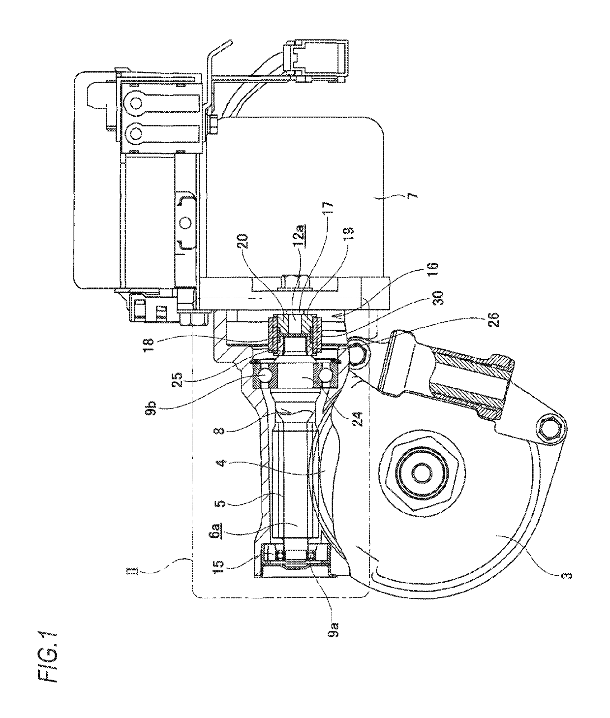
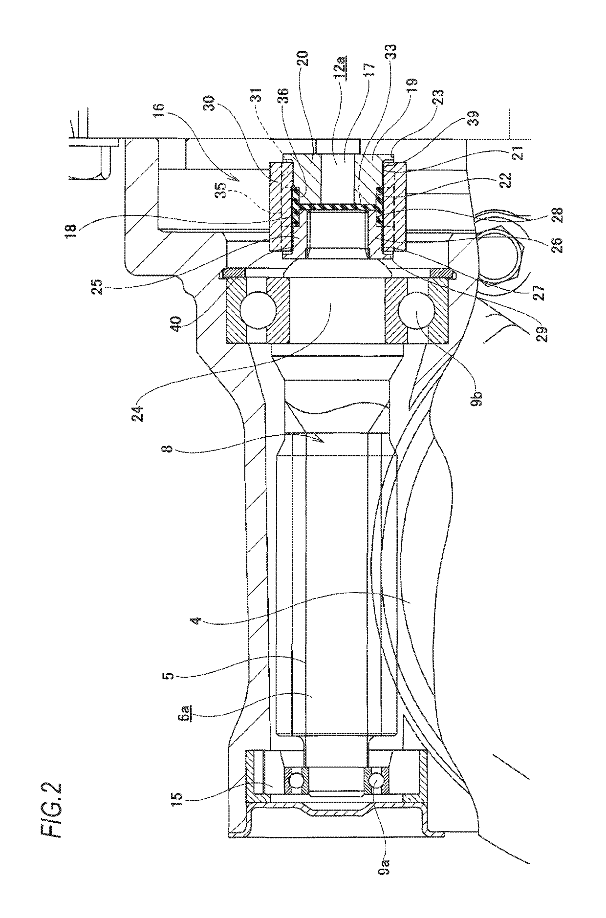
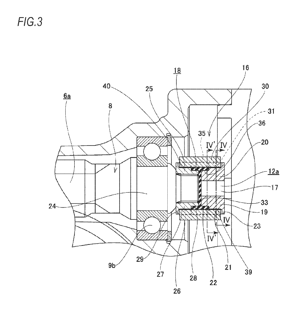
[0070]FIGS. 1 to 8 show a first embodiment of the present invention. The features of the present invention, including the first embodiment, are to implement a structure capable of suppressing generation of an abnormal noise such as gear striking noise when changing a rotational direction of an output shaft, which is a driving shaft, of an electric motor. In an electric power steering device of the first embodiment, a front end portion of a steering shaft 2 configured to rotate in a predetermined direction by a steering wheel 1 is rotatable supported within a housing 3, and a worm wheel 4 is fixed to this part, similarly to the conventional structure shown in FIGS. 21 and 22. Worm teeth 5 configured to mesh with the worm wheel 4 are provided on an axially intermediate portion of a worm shaft 6a. Both axial end portions of a worm 8 configured to rotate by an electric motor 7 are rotatably supported in the housing 3 by a pair of rolling bearings 9a, 9b. Further, a preload applying mech...

second embodiment

[0092]FIGS. 9 to 16 show a second embodiment of the present invention. A torque transmission joint 16a of the second embodiment has a driving-side transmission portion 20a, a driven-side transmission portion 26a, a coupling 30a and an elastic member 18a.

[0093]The driving-side transmission portion 20a is provided at the tip portion of the output shaft main body 17 of the output shaft 12a by supporting a driving-side transmission member 19a, which is provided separately from the output shaft main body 17, by interference fit, spline fitting or the like at a state where rotation can be made in synchronization with the output shaft 12a and axial displacement relative to the output shaft 12a is restricted. As shown in FIG. 13, the driving-side transmission member 19a has a driving-side cylindrical part 62 having a driving-side engagement hole 61 formed at a center portion, a driving-side concave-convex portion 39a configured by driving-side convex portions 63, 63 provided at a plurality...

third embodiment

[0118]Subsequently, the torque transmission joint according to a third embodiment of the present invention is described. In the second embodiment, the elastic bodies 46a, 46b configuring the elastic member 18a and the coupling 30a are separately assembled. However, in the third embodiment, the elastic bodies 46a, 46b are affixed to the coupling 30a. Since the other configurations are the same as the second embodiment, the descriptions are made with reference to FIGS. 9 to 16 of the second embodiment.

[0119]Specifically, in the third embodiment, the pair of elastic bodies 46a, 46b configuring the elastic member 18a is affixed to the coupling 30a by welding or adhesion using an adhesive or the like. That is, the circumferential side surfaces of the engagement pieces 34a, 34a (the circumferential wall portions 37a, 37a) configuring one elastic body 46a are affixed to the circumferential side surfaces of the protrusions 45, 45 provided at the other axial end portion of the coupling 30a. ...


PUM


Abstract

A driving-side transmission portion of an output shaft of an electric motor and a driven-side transmission portion of a worm shaft are coupled to each other via a torque transmission joint including an elastic member and a coupling such that the torque can be transmitted. One axial end portion of a coupling-side concave-convex portion of the coupling is engaged with a first driving-side concave-convex portion of the driving-side transmission portion with a gap in the circumferential direction, and the other axial end portion thereof is engaged with a first driven-side concave-convex portion of the driven-side transmission portion with a gap in the circumferential direction. The elastic member is provided between an axial center portion of the coupling-side concave-convex portion, and a second driving-side concave-convex portion of the driving-side transmission portion and a second driven-side concave-convex portion of the driven-side transmission portion such that the torque can be transmitted respectively.

Description

TECHNICAL FIELD[0001]The present invention relates to a torque transmission joint which is to be incorporated into various mechanical devices and used for transmission of torque between a driving shaft and a driven shaft. The present invention also relates to an electric power steering device which is to be used as a steering device of an automobile and is configured to use an electric motor as an auxiliary power source, thereby reducing a force necessary for a driver to operate a steering wheel.BACKGROUND ART[0002]When applying a steering angle to steered wheels of an automobile (generally, front wheels except for a special vehicle such as a forklift), a power steering device has been widely used as a device for reducing a force necessary for a driver to operate a steering wheel. As such power steering device, an electric power steering device configured to use an electric motor as an auxiliary power source has also been recently used. Various structures have been known for the ele...

Claims


Application Information

Patent Timeline
Patent Type & Authority Patents(United States)
IPC IPC(8): F16D3/68F16D3/74F16D3/54B62D5/04
CPCF16D3/68B62D5/04F16D3/74F16D3/54B62D5/0454B62D5/0409
Inventor SEGAWA, TORUOOSAWA, RYOU
Owner NSK LTD
Why Eureka
Try Eureka