
Antenna device and antenna device control method

a technology of antenna device and control method, which is applied in the direction of antenna, antenna details, electrical apparatus, etc., to achieve the effect of high transmission and reception level and accurate adjustment of antenna position

Inactive Publication Date: 2019-05-07
NEC CORP
View PDF23 Cites 0 Cited by
  • Summary
  • Abstract
  • Description
  • Claims
  • Application Information

AI Technical Summary

Benefits of technology

The solution enables precise adjustment of the antenna position to maintain high transmission and reception levels even under severe environmental conditions, such as high winds or disasters, without disconnecting communication.

Problems solved by technology

However, even when the antenna is set up in an appropriate direction, there are various factors to cause a change in the direction of the antenna by environmental effects after the installation, such as the deformation of an antenna installation base due to high winds or sunshine, earthquake shock or the like, for example.

Method used


Image

  • Antenna device and antenna device control method
  • Antenna device and antenna device control method
  • Antenna device and antenna device control method

Examples


first exemplary embodiment

[0024]The structure of an antenna device 100 according to a first exemplary embodiment of the present invention is described hereinafter with reference to the drawings.

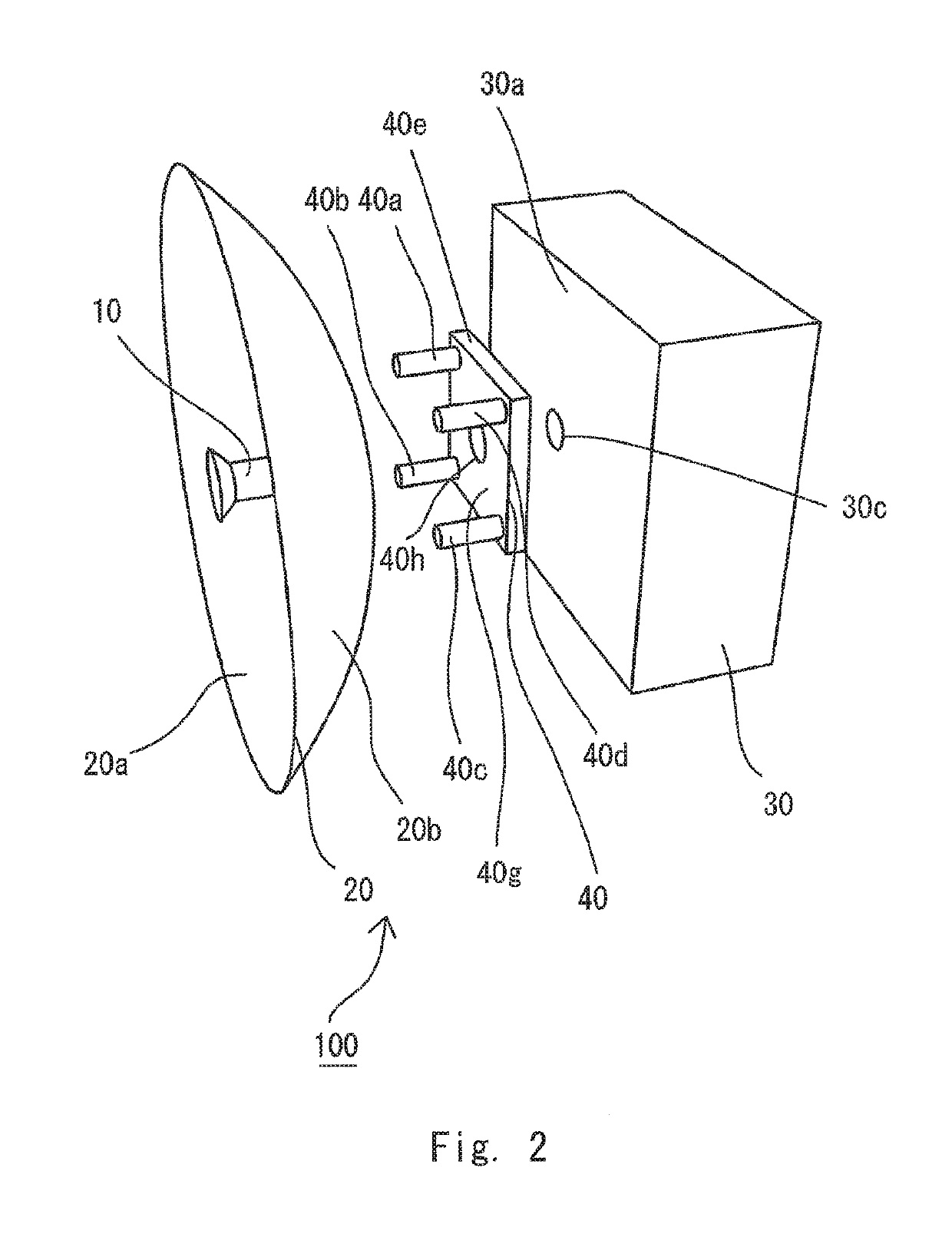
[0025]As shown in FIGS. 1 and 2, the antenna device 100 is mounted on a pole 50 whose base end 50a is fixedly installed on a floor. Specifically, a backside 30b of a housing 30 is fixedly installed on a middle of the pole 50. The housing 30 is a rectangular box that is rigid and resistant to deformation, for example. A transmitting and receiving circuit 60 that transmits and receives radio waves is housed and fixed in the housing 30. The housing 30 is a part of an outdoor device, for example. A backside 20b of an antenna member 20 is coupled to a front side 30a of the housing 30a though a coupling means 45, which is not shown.

[0026]The antenna member 20 is thereby coupled to the housing 30 in the way it is freely rotatable about the coupling means as the center of rotation in a certain angle range in the pitching and ...

second exemplary embodiment

[0054]An antenna device 200 according to a second exemplary embodiment of the present invention is described hereinafter with reference to the drawings.

[0055]The antenna device 200 according to this exemplary embodiment has the same structure as the one according to the first exemplary embodiment, and the same reference symbols are used for the description of the same elements, and the description of a redundant part is omitted.

[0056]In the first exemplary embodiment, the angle calculation means 81 calculates the tilt angle of the housing 30 based on the acceleration detected by the acceleration detection means 80 and uses the tilt angle for the calculation of the relative angle. However, in the actual environment where the antenna device 100 is placed, the detected acceleration contains noise. As described earlier, because the angle calculation means 81 calculates the tilt angle by performing integration of acceleration, there is a problem that, if integration of noise level accele...


PUM


Abstract

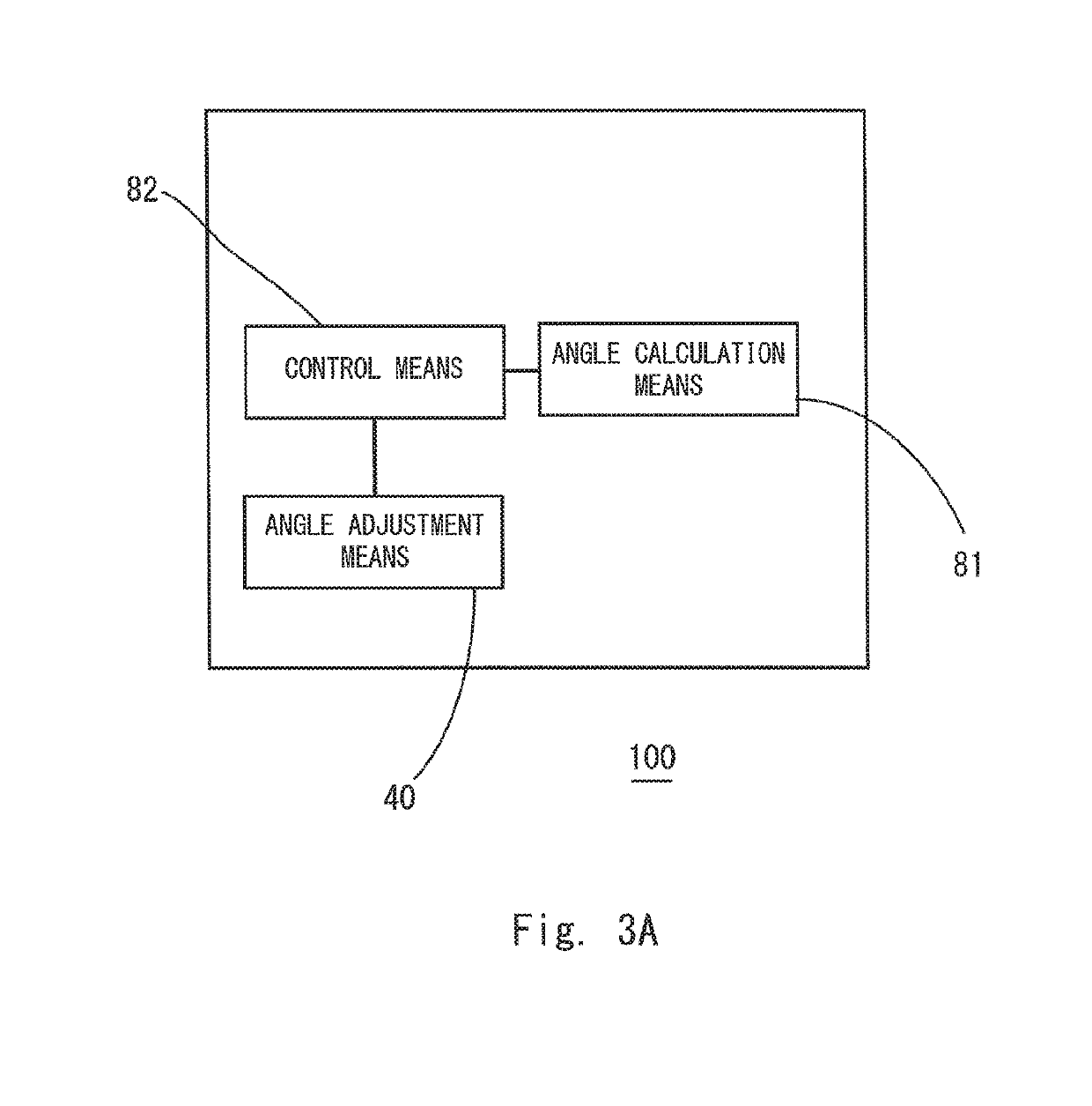
An antenna device (100) according to the present invention includes a primary radiation means (10) for guiding and emitting radio waves at transmission, and guiding radio waves at reception, an antenna member (20) for reflecting radio waves emitted by the primary radiation means (10) and forming a transmission beam at transmission, and reflecting received waves on the primary radiation means (10) at reception, an angle adjustment means (40) for changing a relative angle between the primary radiation means (10) and the antenna member (20), an angle calculation means (81) for calculating the relative angle to be formed between the primary radiation means (10) and the antenna member (20) for displacement of an azimuth occurring in the primary radiation means (10), and a control means (82) for controlling the angle adjustment means based on the calculated relative angle.

Description

CROSS-REFERENCE TO RELATED APPLICATIONS[0001]This application is a national stage application of International Application No. PCT / JP2015 / 000418 entitled “ANTENNA DEVICE AND ANTENNA DEVICE CONTROL METHOD,” filed on Jan. 30, 2015, which claims the benefit of the priority of Japanese Patent Application No. 2014-027795 filed on Feb. 17, 2014, the disclosures of each of which are hereby incorporated by reference in their entirety.TECHNICAL FIELD[0002]The present invention relates to an antenna device and an antenna device control method and, particularly, to an antenna device and an antenna device control method that adjust the azimuth of an antenna.BACKGROUND ART[0003]A wireless communication system that wirelessly communicates between a wireless base station and another wireless base station without using a communication cable is known. An opposite antenna having directionality is used for this communication. To perform communication using a directional antenna, it is important that t...

Claims


Application Information

Patent Timeline
Patent Type & Authority Patents(United States)
IPC IPC(8): H01Q1/12H01Q3/20H01Q15/16H01Q19/13H04W88/08
CPCH01Q3/20H01Q1/1257H01Q19/13H01Q15/16H04W88/08
Inventor TANAKA, NOBUYUKI
Owner NEC CORP
Learn More