
Portable arm movement exercise device utilizing centripetal and reactive centrifugal force principles

a technology of centrifugal force and exercise device, which is applied in the field of portable arm movement exercise device utilizing centripetal and reactive centrifugal force principles, can solve the problems of device stationary and inability to be easily transported by the user, and devices as well as their allowance are limited, so as to increase the torque on the user's muscles, provide stress and resistance to the arm and shoulder muscles, and high torque levels

Active Publication Date: 2019-05-07
MCCALEB KYLE DAVID
View PDF37 Cites 1 Cited by
  • Summary
  • Abstract
  • Description
  • Claims
  • Application Information

AI Technical Summary

Benefits of technology

The invention is a training device for baseball and other sports that helps develop arm strength and flexibility through a process of muscle treatment. It provides high torque levels during use and can be adjusted to different user needs. The device allows for an exaggerated throwing motion, reducing stress on the arm and shoulder muscles. It also helps increase the strength and flexibility of all muscle groups over time. The grip portion is designed to be attached to the flexible shaft and can be of any shape or configuration that meets the user's requirements. The weight portion can be a combination of a spherical object and discs or other weighted objects, secured through the same means for securing the spherical object. The support structure can be a soft elastomeric material to reduce discomfort during use. The device helps alleviate the stress and pressure on the arm and shoulder muscles and can be used in various sports to improve arm strength and flexibility.

Problems solved by technology

A plethora of such devices are stationary and unable to be easily transported by the user from one location to another.
As such, these devices typically engender a weight system attached to a lifting mechanism provided within a rather large and bulky overall system or attached to a wall or other stationary implement, such as a bar (for instance, as in U.S. Pat. No. 4,974,836, to Hirsch).
Such devices, as well, do not include any manner of compensating for phenomena such as arc movement and centripetal forces as the stationary systems require a repetitive range of motions that rely upon the stationary basis of the device itself.
Other devices have allowed for free ranges of motions through their portability; however, such devices as well are limited in their allowance of the overall range of potential arc motions that are available the user over the entirety of his or her arms and / or shoulders.
Such a device, however, is further limited by the rigidity of the extension as well as the relatively short length of such an extension, thereby limiting the overall effect available for the user, in combination with the hammer movement undertaken by the user.
Such limited devices thus evince drawbacks as the possible muscle treatments that are available through their utilization are based on rigid formats, rather than flexible arcs that accord stronger, yet more even forces over the range of a user's arm and shoulder muscles during use.
To date, no other device in the industry allows for the same level of muscle treatments.
The important issue is the length of the shaft and the flexibility thereof that ultimately accords, during exercise and use thereof in the aforementioned throwing or swinging motion, exaggerated levels of torque to the user's arm and shoulder muscles to develop and flex such groups, while minimizing the overall stress on the joints, ligaments, and tendons in the same vicinity.
Too long a device will result in difficulty for the user in actuality maneuvering the device without injuring himself or herself during use.

Method used


Image

  • Portable arm movement exercise device utilizing centripetal and reactive centrifugal force principles
  • Portable arm movement exercise device utilizing centripetal and reactive centrifugal force principles
  • Portable arm movement exercise device utilizing centripetal and reactive centrifugal force principles

Examples


Embodiment Construction

[0027]The invention is best explained through the following drawings showing potentially preferred embodiments of the inventive device. In no way are such depictions intended to limit the scope of the device itself as the ordinarily skilled artisan should understand suitable alternatives thereto that fall within the breadth of the overall invention without having to provide every possible permutation thereof within this description.

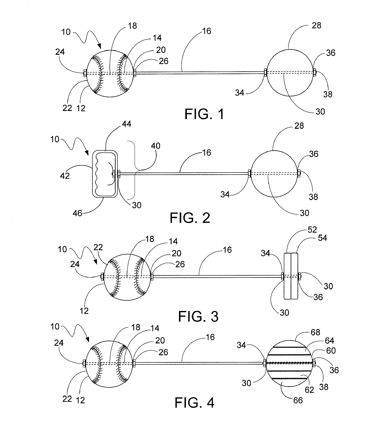
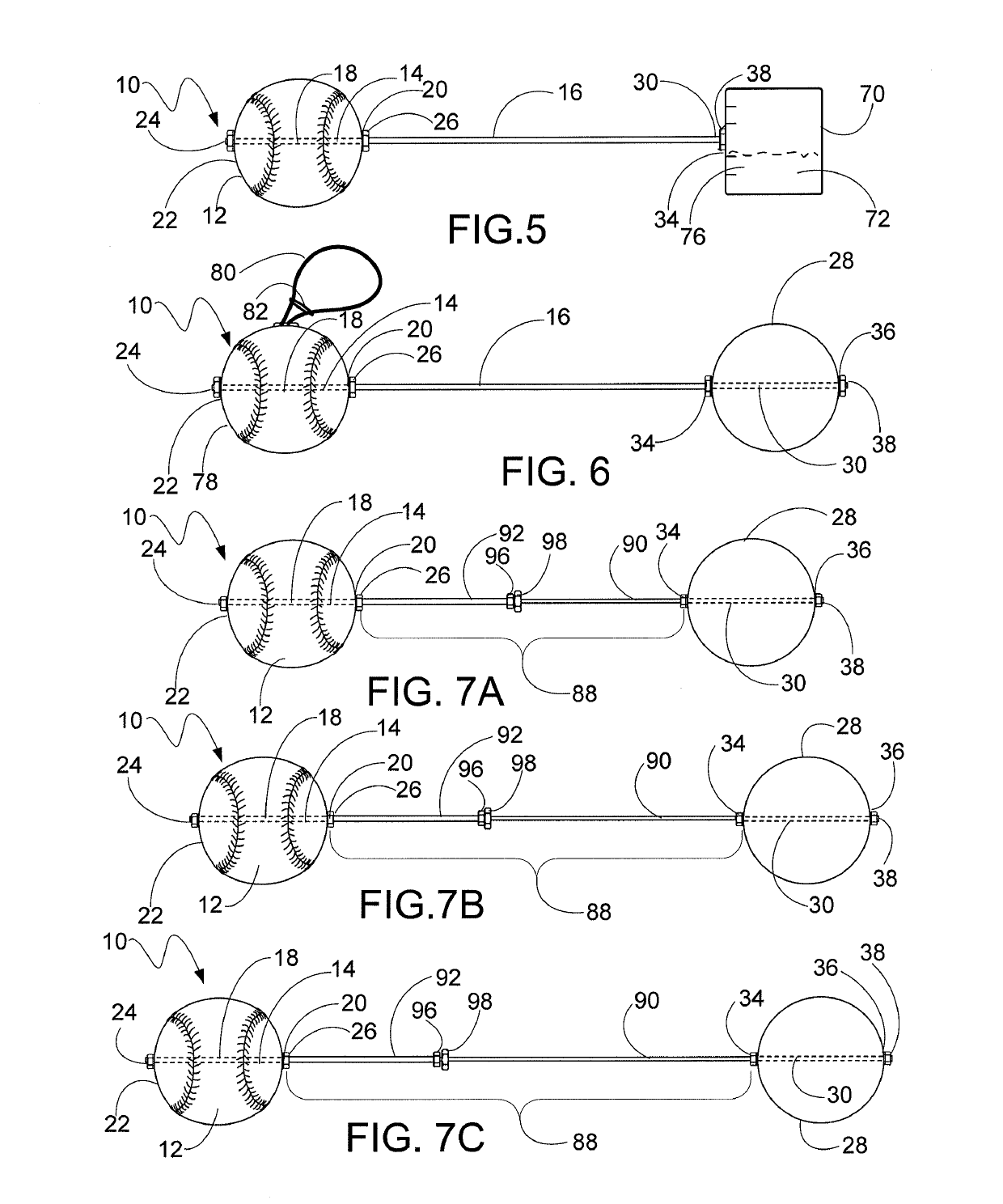
[0028]As noted above, FIG. 1 shows a side view of the overall device 10 including a spherical grip portion 12 (here a regulation size baseball) through which a first end 14 of a flexible rod 16 (here shown at an overall length of 18 inches, or about 45 centimeters) is present within a tunnel 18 created therein with an inner opening 20 and an outer opening 22. The flexible rod 16 is cylindrical in shape in this instance with a diameter of ½ inch (12.7 centimeters) and is made of compressed nylon strands (such as a nylon rod from Rutland; alternatively, a s...


PUM


Abstract

A device to strengthen a person's arm muscles through the utilization of a portable device including a handle portion and a weight component with the two components separated by a flexible rod. Such a device allows for the user to grip the handle portion and act as if they are throwing such a handle portion while the weight end moves along an arc defined through the length of the flexible rod. The resultant action is the generation of centripetal force along the defined arc with the reactive centrifugal force providing resistance to the user's arm muscles in a manner that is unique and heretofore unattainable through the utilization of a portable exercise device. The flexible rod component provides at least 10 inches (25.4 cm) of spacing between the handle portion (which may be in the form of a sphere, such as a baseball or softball, or a handle, or any other typical implement that a person may throw or swing) and the weight portion (which may be of any configuration to permit increase or decrease of the weight present thereon).

Description

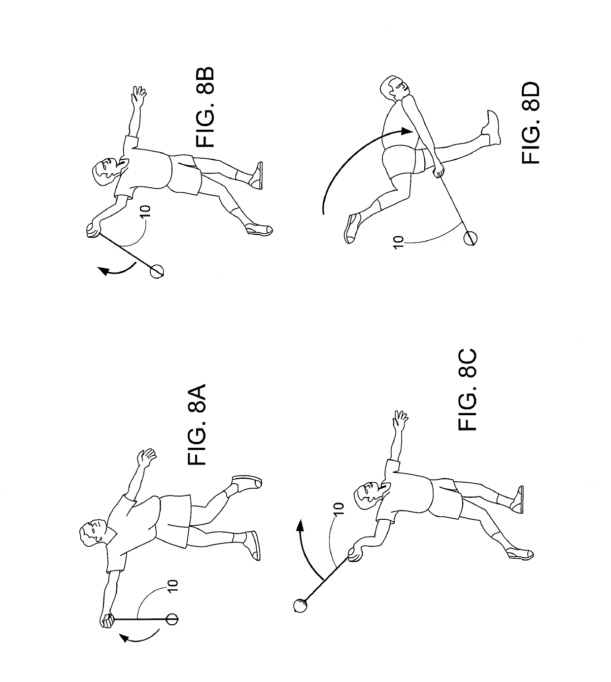
CROSS-REFERENCE TO RELATED APPLICATION[0001]This application is the conversion of U.S. Provisional Patent Application No. 61 / 311,688, filed on Mar. 8, 2010. Applicant claims priority from such provisional application and the entire application is referenced in its entirety herein.FIELD OF THE INVENTION[0002]This invention pertains to a device to strengthen a person's arm muscles through the utilization of a portable device including a handle portion and a weight component with the two components separated by a flexible rod. Such a device allows for the user to grip the handle portion and act as if they are throwing such a handle portion while the weight end moves along an arc defined through the length of the flexible rod. The resultant action is the generation of centripetal force along the defined arc with the reactive centrifugal force providing resistance to the user's arm muscles in a manner that is unique and heretofore unattainable through the utilization of a portable exerci...

Claims


Application Information

Patent Timeline
IPC IPC(8): A63B69/00
CPCA63B69/0002A63B21/06A63B21/00043A63B21/0608A63B2069/0006A63B2209/00A63B71/0054A63B2225/09A63B2210/50A63B65/12A63B69/0091
Inventor MCCALEB, KYLE DAVID
Owner MCCALEB KYLE DAVID
Learn More