
Medical balloon devices and methods

a technology of balloons and balloons, applied in the field of balloon devices, can solve the problems of less than optimal, limited longitudinal distension of the balloon wall, extra processing steps, etc., and achieve the effect of less material bulk and smaller diameter

Active Publication Date: 2019-05-07
WL GORE & ASSOC INC
View PDF145 Cites 10 Cited by
  • Summary
  • Abstract
  • Description
  • Claims
  • Application Information

AI Technical Summary

Benefits of technology

This patent describes balloon devices that have variations in their stiffness along their length or circumference. The stiffness can be patterned to control the deployment of the balloon device or to control blood flow during angioplasty. The balloon or balloon cover can be made of a composite material that includes an expanded polymer membrane and an elastomer. The composite material can have a stop point beyond which further expansion is inhibited. The balloon with a reduced infolding has a smaller profile.

Problems solved by technology

Balloons of this construction have some limitations which make them less than optimal.
For example, because the strong direction of the anisotropic film provides strength to the balloon wall in the longitudinal direction, the balloon wall is limited in its ability to distend in the longitudinal direction to account for inflation.
This inability to distend longitudinally and the tendency to foreshorten impacts the ability to inflate fully and causes unwanted stress on the material some of which is transferred to the catheter causing buckling and in the case of a cover, to the underlying balloon causing cone rounding.
However, this is an extra processing step, and adds bulk to the cover.
Also, this extra length that can be stored is relatively mobile and can migrate / bunch undesirably during processes such as sheath insertion.
Another limitation of the above described constructs relate to the weak direction being oriented circumferentially.
Such balloon or balloon covers have a very limited ability to influence the final burst properties of the balloon as the material will continue to distend until it splits with very little force.

Method used


Image

  • Medical balloon devices and methods
  • Medical balloon devices and methods
  • Medical balloon devices and methods

Examples


example 1

[0082]An elastomeric composite material was made in the following manner.

[0083]Precursor Membrane

[0084]A biaxially expanded ePTFE membrane that had not been amorphously locked and had the following properties was obtained: thickness was approximately 0.001 mm, density was approximately 0.964 g / cc, matrix tensile strength in the strongest direction was approximately 451 MPa, matrix tensile strength in the direction orthogonal to the strongest direction was approximately 320 MPa, elongation at maximum load in the strongest direction was approximately 92%, and elongation at maximum load in the direction orthogonal to the strongest direction was approximately 142%. Upon tensioning by hand, the membrane did not noticeably retract upon the release of the tension.

[0085]Retracted Membrane

[0086]A roll of precursor membrane where the length direction corresponded with the weakest direction of the membrane was restrained in the clamps of a heated, uniaxial tenter frame and fed into the heated ...

example 2

[0092]A balloon cover was constructed in the following manner. An ePTFE-fluoropolymer elastomeric composite material as described in detail above was obtained. A mandrel sized to delivery diameter, approximately 4.3 mm is obtained. It was noted that the length direction of the composite material was the direction that possessed the elastomeric properties.

[0093]The composite material was cut to 100 mm width, measuring in the machine direction. The composite material was cut to 250 mm length, measuring in the transverse direction. The 250 mm length was then cut into two, 125 mm lengths, measuring in the transverse direction.

[0094]The composite material was aligned so that the 4.3 mm mandrel was parallel with the machine direction of the material. The film was then circumferentially wrapped about the mandrel with the side of the membrane opposing the imbibed elastomer oriented toward the mandrel. The second 125 mm length was then circumferentially wrapped about the mandrel with the sid...

example 3

[0097]A balloon cover was constructed in the following manner. An ePTFE-fluoropolymer elastomeric composite material was obtained. This composite utilized an expanded ePTFE membrane—made generally in accordance with U.S. Pat. No. 5,476,589 to Bacino which is hereby incorporated by reference in its entirety—had the following properties: thickness was approximately 6.3 μm, mass per area was approximately 3 g / m2, matrix tensile strength in the strongest direction was approximately 917 mPa, matrix tensile strength in the direction orthogonal to the strongest direction was approximately 17.2 mPa. The membrane was coated similarly to the composite of Example 1. A mandrel sized to delivery diameter, approximately 4.3 mm is obtained.

[0098]The composite material was cut to 100 mm width, measuring in the machine direction. It is noted that this width direction is the strongest direction. The composite material was cut to 250 mm length, measuring in the transverse direction. The 250 mm length ...


PUM

PropertyMeasurementUnit
widthaaaaaaaaaa
widthaaaaaaaaaa
widthaaaaaaaaaa

Abstract

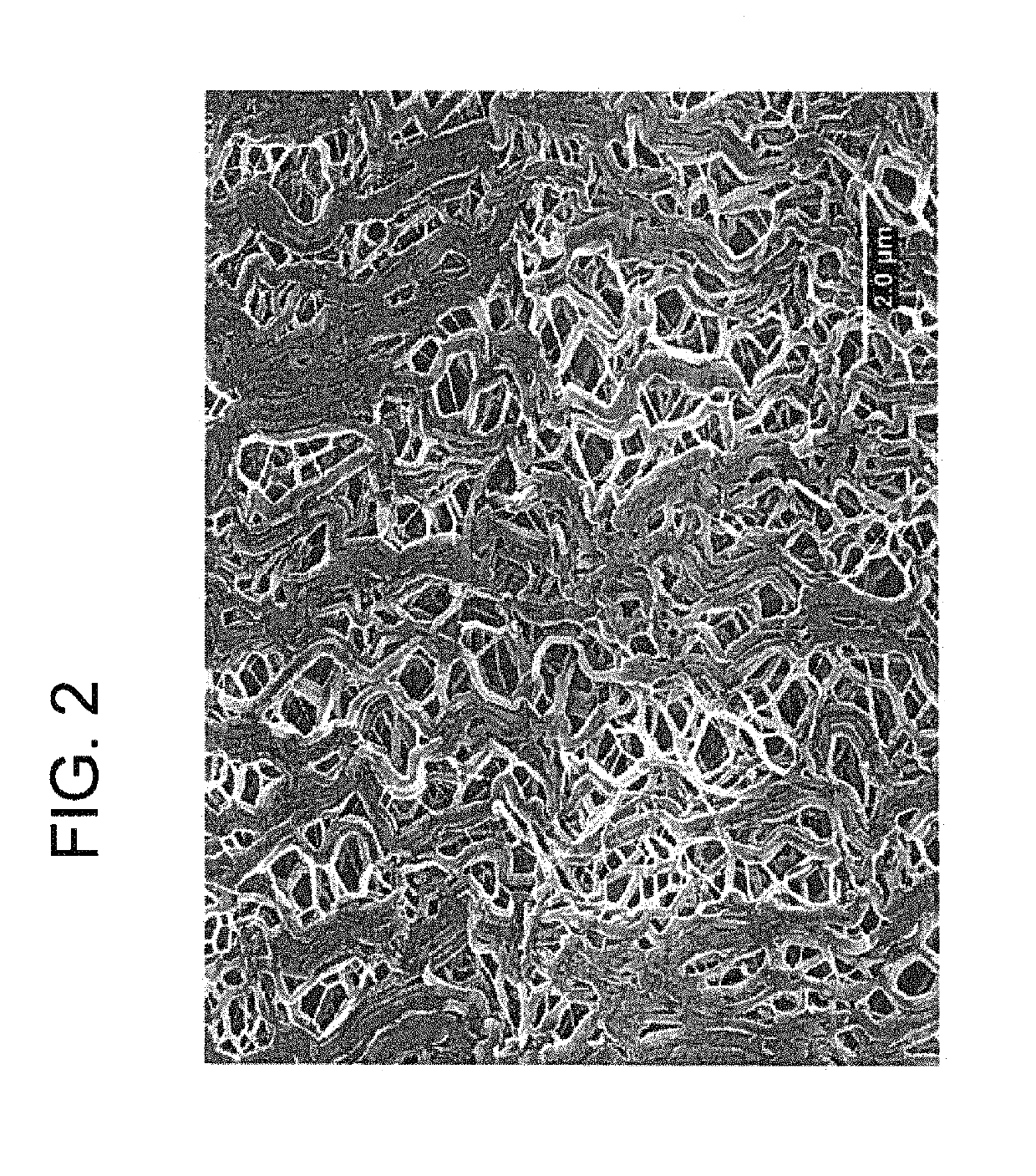
A balloon or balloon cover comprising a composite material having a least one expanded fluoropolymer material and an elastomer is provided. The expanded fluoropolymer material can contain serpentine fibrils. In exemplary embodiments, the fluoropolymer is polytetrafluoroethylene. The composite material may be axially, helically, and / or circumferentially wrapped to form a balloon or balloon cover. The balloon or balloon cover exhibits a sharp increase in stiffness at a predetermined diameter. The balloon or balloon cover can be designed to have a stop point in either a radial or axial direction.

Description

FIELD[0001]The present disclosure relates generally to balloon devices that are radially distensible up to a stop point in addition to being longitudinally distensible. The present disclosure relates generally to balloon devices that include (1) an expanded polytetrafluoroethylene (ePTFE) membrane material containing serpentine fibrils and (2) an elastomer.DEFINITIONS[0002]As used herein, the term “serpentine fibrils” means multiple fibrils that curve or turn one way then another.[0003]As used herein, the term “controlled retraction” refers to causing articles to shorten in length in at least one direction by the application of heat, by wetting with a solvent, or by any other suitable means or combinations thereof in such a way as to inhibit folding, pleating, or wrinkling of the subsequent article visible to the naked eye.[0004]The term “imbibed or imbibing” as used herein is meant to describe any means for at least partially filling at least a portion of the pores of a porous mate...

Claims


Application Information

Patent Timeline
Patent Type & Authority Patents(United States)
IPC IPC(8): A61M29/00A61F2/958A61L29/06A61M25/10
CPCA61L29/06A61F2/958A61M25/10A61M2025/1086A61M25/1029A61M2025/1084
Inventor GOEPFRICH, JAMES L.HAARER, JOSHUA C.HEDBERG, BRANDON C.TRAPP, BENJAMIN M.
Owner WL GORE & ASSOC INC
Learn More