Die cushion device of press machine

a press machine and die cushion technology, applied in the direction of springs/dampers, vibration suppression adjustments, manufacturing tools, etc., can solve the problems of inability to apply predetermined die cushion force to material with (greatly) different plate thicknesses, and inability to allow the plurality of die cushion devices to serve as die cushion devices, etc., to achieve the effect of improving the function of applying uniform die cushion force and higher accuracy

Active Publication Date: 2019-04-16
AIDA ENG LTD
View PDF16 Cites 0 Cited by
  • Summary
  • Abstract
  • Description
  • Claims
  • Application Information

AI Technical Summary

Benefits of technology

[0010]Patent Literature 1 describes not only a basic feature of a servo die cushion device that can provide arbitrary cushioning action, but also features of enabling downsizing and a low price of the entire device as compared with a conventional device that provides cushioning action by using an air cylinder and a hydraulic cylinder, and of enabling a work tending to easily wrinkle or crack, such as aluminum, to be prevented from wrinkling or cracking by cushioning action independently controlled by a servo motor for each pad while there is no description of reason.

Problems solved by technology

Unfortunately, although the die cushion device described in Patent Literature 1 uses rack-and-pinion mechanisms that drive the respective pad members, the plurality of rack-and-pinion mechanisms is mechanically synchronized with each other with a joint and an engaged gear train.
As a result, it is impossible to allow the die cushion device to serve as a plurality of die cushion devices capable of setting a die cushion stroke and die cushion force, different for each of the pad members, even if the die cushion device is controlled by making any originality and ingenuity.
In addition, a plurality of drive shafts of the rack-and-pinion mechanisms, driving the respective pad members, has a “play” of a backlash of the gear train at most, and thus it is impossible to apply predetermined die cushion force to material with (greatly) different plate thickness for each portion on a surface of the cushion pad, such as tailored blank material, or to a blank holder (to which shim adjustment is applied) inclined in a side-to-side direction or a fore-and-aft direction, without causing mechanical strain.

Method used


Image

  • Die cushion device of press machine
  • Die cushion device of press machine
  • Die cushion device of press machine

Examples


first embodiment

of Die Cushion Controller

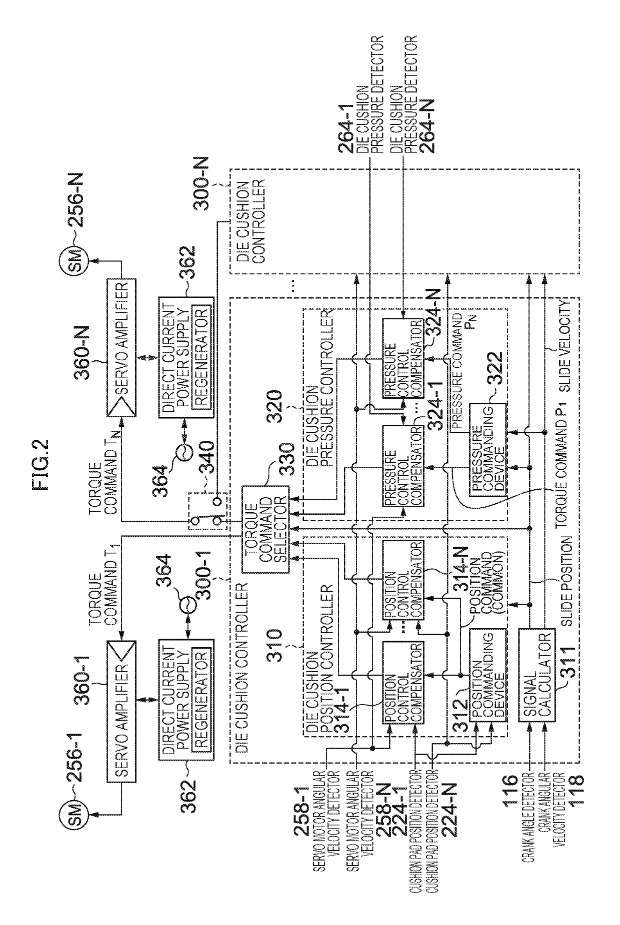
[0094]FIG. 2 is a block diagram illustrating a first embodiment of the die cushion controller 300 in the die cushion device 200 illustrated in FIG. 1.

[0095]The die cushion controller 300 includes the number of die cushion controllers 300-1 to 300-N, corresponding to the number of the cushion pads 210-1 to 210-N. In particular, the die cushion controller 300 of the first embodiment is shown in the case where a torque command N selector 340 selects the die cushion controller 300-1 to control the plurality of cushion pads 210-1 to 210-N as one (multi-axis (N-axis) synchronization type) servo die cushion device.

[0096]Since each of the plurality of die cushion controllers 300-1 to 300-N has the same function, the die cushion controller 300-1 that controls the cushion pad 210-1 will be described.

[0097]The die cushion controller 300-1 includes a die cushion position controller 310, a signal calculator 311, a die cushion pressure controller 320, and a torque command...

second embodiment

of Die Cushion Controller

[0121]FIG. 6 is a block diagram illustrating a second embodiment of the die cushion controller 300 in the die cushion device 200 illustrated in FIG. 5.

[0122]In FIG. 6, the die cushion controller 300 includes the number of die cushion controllers 300-1 to 300-N, corresponding to the number of the cushion pads 210-1 to 210-N. In particular, the die cushion controller 300 of the second embodiment is shown in the case where the torque command N selector 340 selects the die cushion controllers 300-1 to 300-N to control the plurality of cushion pads 210-1 to 210-N as N separate servo die cushion devices.

[0123]A user can select a function of serving as only one servo die cushion device of the first embodiment illustrated in FIG. 2, or a function of serving as N servo die cushion devices of the second embodiment illustrated in FIG. 6, at any time, by switching the torque command N selector 340. Since each of the plurality of die cushion controllers 300-1 to 300-N ha...

third embodiment

Configuration of Die Cushion Device of Third Embodiment

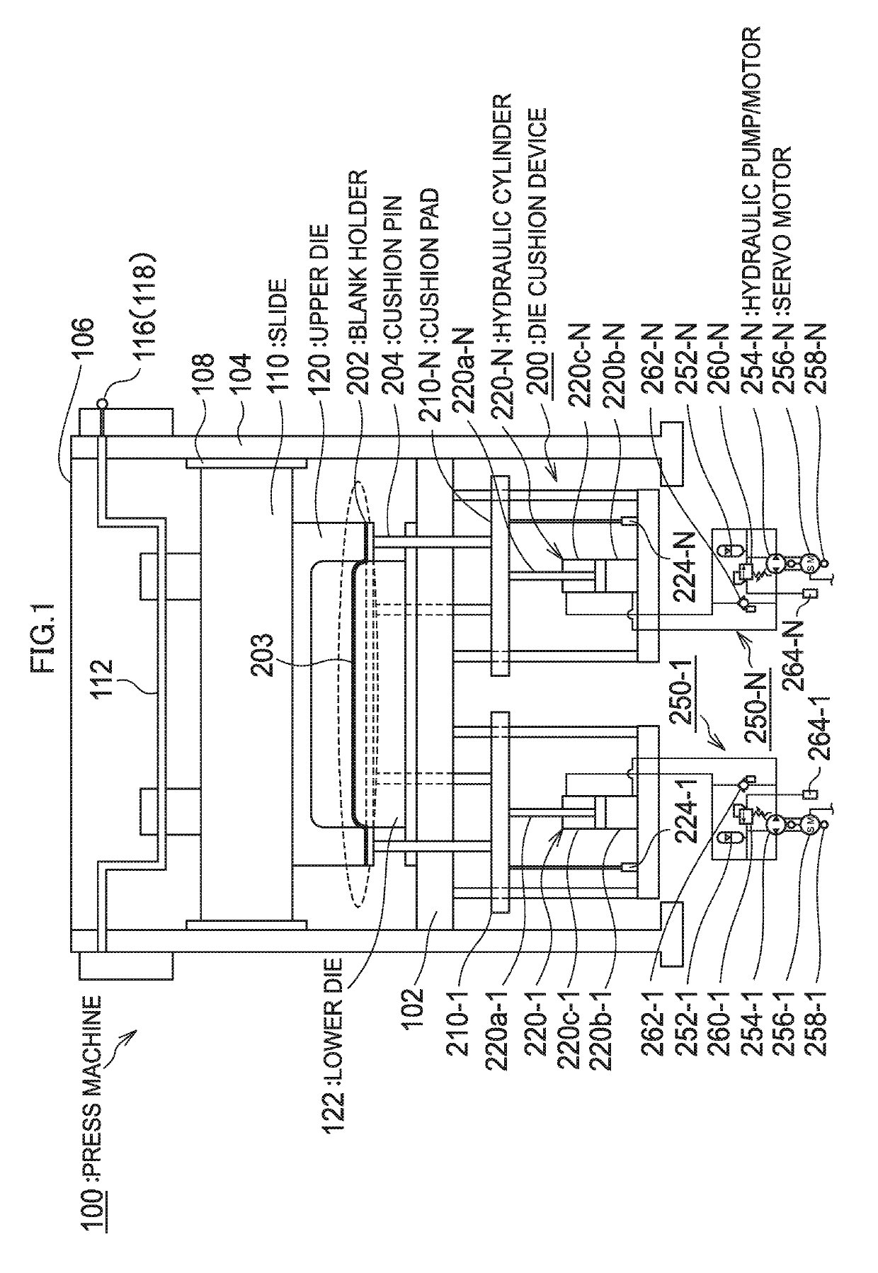
[0137]FIG. 7 is a structural view illustrating a main section of a third embodiment of the die cushion device of a press machine in accordance with the present invention. A portion common to that of the first and second embodiments of the die cushion device of a press machine, illustrated in FIGS. 1 and 5, respectively, is designated by the same reference numeral as that of FIGS. 1 and 5 without duplicated description in detail.

[0138]The die cushion device of a press machine of each of the first and second embodiments has the number of cushion pads 210-1 to 210-N that is the same as the number of hydraulic cylinders 220-1 to 220-N that drives the cushion pads 210-1 to 210-N, as well as that is the same as the number of hydraulic circuits 250-1 to 250-N. Contrarily, the die cushion device of a press machine of the third embodiment illustrated in FIG. 7 is different in that a plurality of hydraulic cylinders 220-1LF (220-1LB) and ...


PUM

PropertyMeasurementUnit
die cushion forceaaaaaaaaaa
cushion forceaaaaaaaaaa
forceaaaaaaaaaa

Abstract

A die cushion device of a press machine includes: a plurality of cushion pads; a plurality of die cushion force generators that supports the plurality of respective cushion pads, and that is capable of independently moving up and down the plurality of respective cushion pads as well as independently generating die cushion force for each of the cushion pads; and a die cushion controller that controls the plurality of die cushion force generators to independently move up and down the plurality of respective cushion pads as well as to independently generate die cushion force for each of the cushion pads.

Description

[0001]This application claims priority to Japanese Patent Application No. 2015-113022, filed on Jun. 3, 2015, the disclosures of each of which are hereby incorporated by reference.BACKGROUND OF THE INVENTION[0002]Field of the Invention[0003]The present invention relates to a die cushion device of a press machine, and more particularly to a die cushion device of a press machine, with a plurality of cushion pads for one press machine.[0004]Description of the Related Art[0005]Heretofore, this kind of die cushion device has been disclosed in Japanese Patent Application Laid-Open No. 06-000543 (Patent Literature 1), Japanese Patent Application Laid-Open No. 07-100552 (Patent Literature 2), and Japanese Patent Application Laid-Open No. 2006-192481 (Patent Literature 3).[0006]Patent Literature 1 describes a die cushion device that includes a plurality of divided cushion pads each of which supports a lower die from below through a cushion pin. Each of pad members is connected to a rack rod ...

Claims


Application Information

Patent Timeline
Patent Type & Authority Patents(United States)
IPC IPC(8): B21D24/14B30B15/02B21D24/10B21D24/02F16F15/027
CPCB21D24/14B21D24/02F16F15/0275B30B15/026B21D24/10B30B15/02B30B15/28
Inventor KOHNO, YASUYUKI
Owner AIDA ENG LTD
Why Eureka
Try Eureka