
Ophthalmological device for treating eye tissue

a technology of eye tissue and laser pulse, which is applied in the field of ophthalmological devices for treating eye tissue with laser pulse, can solve the problems of increasing the distance of the scanner system from the virtual entry pupil, increasing the cost, and increasing the complexity of control and additional scanner systems

Active Publication Date: 2019-04-02
ZIEMER OPHTHALMIC SYST
View PDF13 Cites 0 Cited by
  • Summary
  • Abstract
  • Description
  • Claims
  • Application Information

AI Technical Summary

Benefits of technology

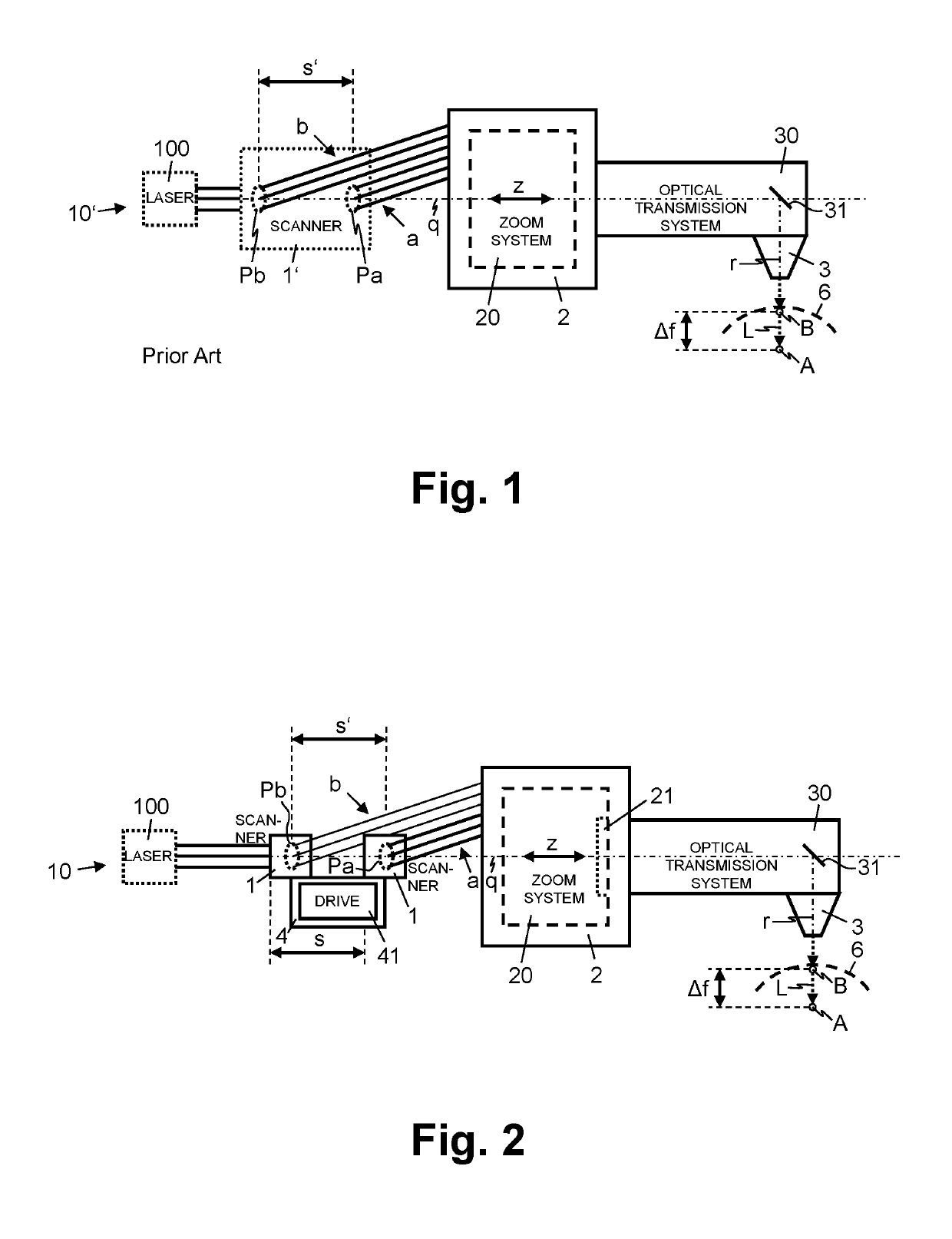
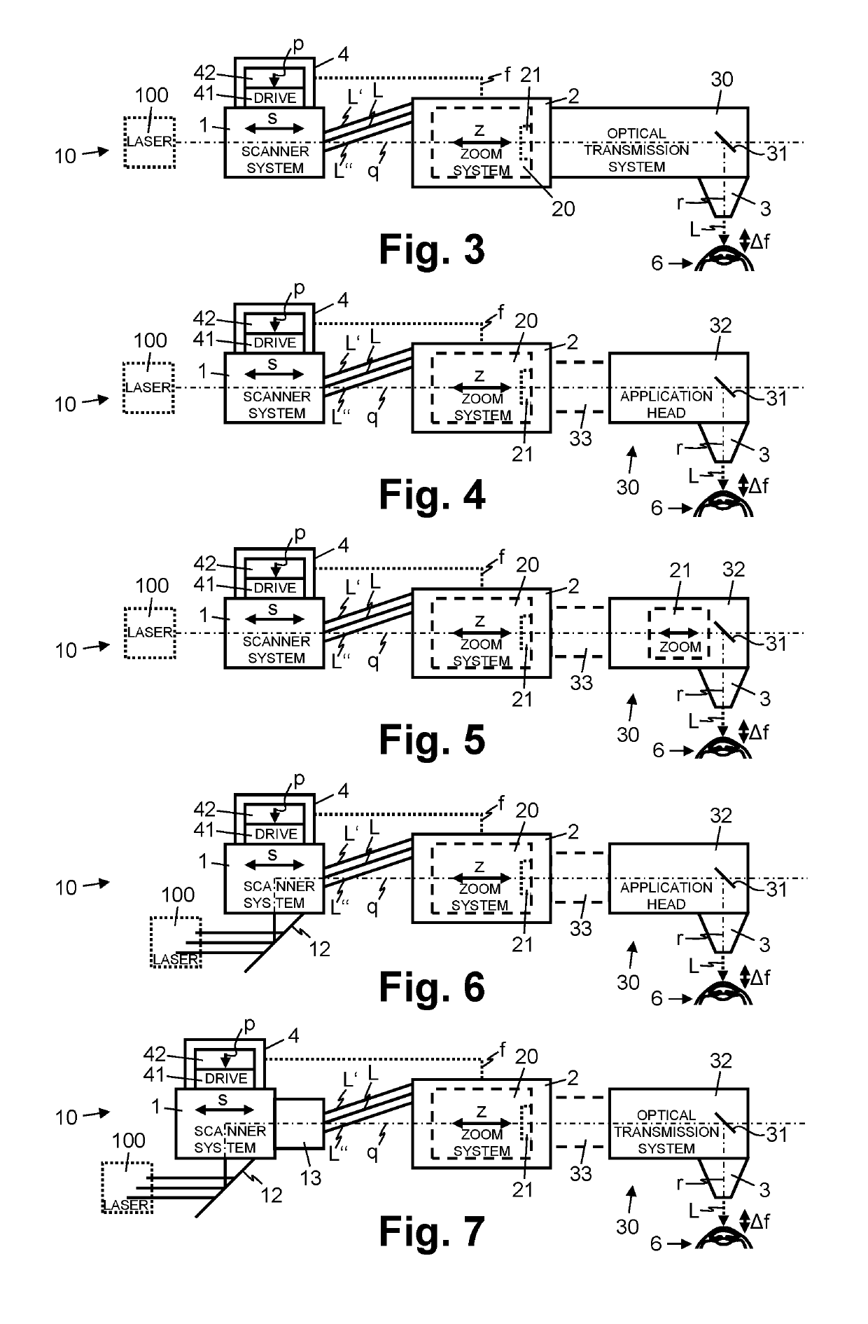
The present invention proposes an ophthalmological device for treating eye tissue with laser pulses that reduces the need for larger and additional scanner mirrors. The device allows for adjustment of the focus position of the laser pulses without the need for enlarged and additional scanner mirrors. A simple displacement movement of the scanner system is used to connect it to the zoom system, reducing the thermal load on the optical systems and the need for complex control algorithms. The device also allows for a reduction in the instrument costs overall and higher dynamics (speed) by using small mirrors. The displacement device can be configured to displace the scanner system based on the position of a virtual entry pupil of the zoom system, allowing for precise positioning of the deflection mirrors.

Problems solved by technology

Here, depending on the current setting of the zoom system, this causes increased distances of the scanner system from the virtual entry pupil of the zoom system.
The upshot of this is that the zoom system must have a design with the larger diameter and hence it is more expensive (the costs increase at least with the square of the diameter).
However, in this case, the advantage of a more compact optical system is bought by the disadvantage of a significantly increased control complexity and additional scanner systems.

Method used


Image

  • Ophthalmological device for treating eye tissue
  • Ophthalmological device for treating eye tissue

Examples


Embodiment Construction

[0005]It is an object of the present invention to propose an ophthalmological device for treating eye tissue with laser pulses, which does not have at least some of the disadvantages of the known systems. In particular, it is an object of the present invention to propose an ophthalmological device for treating eye tissue with laser pulses, which enables an adjustment of the focus position of the laser pulses in the projection direction, without having to provide enlarged and / or additional scanner mirrors to this end or minimize the diameter and the size of the zoom system.

[0006]In accordance with the present invention, these goals are achieved by the features of the independent claims. Further advantageous embodiments moreover emerge from the dependent claims and the description.

[0007]An ophthalmological device for treating eye tissue with laser pulses comprises a scanner system for dynamically deflecting the laser pulses, a projection optical unit for focused projection of the lase...


PUM


Abstract

An ophthalmological device (10) for treating eye tissue (6) with laser pulses (L) comprises a projection optical unit (3) for focused projection of the laser pulses (L), a scanner system (1) for dynamically deflecting the laser pulses (L) and a zoom system (20), which is arranged between the projection optical unit (3) and the scanner system (1) and which is configured to adjust the focused projection of the laser pulses (L) in the projection direction (r) in different zoom settings (z). The ophthalmological device (10) moreover comprises a displacement device (4), which is configured to displace the scanner system (1) depending on the zoom setting (z) of the zoom system (20). What the displacement (s) of the scanner system (1) coupled to the zoom setting (z) of the zoom system (20) renders possible is the adaptation of the position of the scanner system (1) in a dynamic and synchronized fashion to the setting of the zoom system (20) and hence to the current position of the virtual entry pupil (Pa, Pb) of the zoom system (20).

Description

CROSS REFERENCE TO RELATED APPLICATIONS[0001]The present application claims benefit of U.S. Provisional Application No. 61 / 753,141, filed Jan. 16, 2013, the disclosure of which is incorporated herein by reference.TECHNICAL FIELD[0002]The present invention relates to an ophthalmological device for treating eye tissue with laser pulses. The present invention more particularly relates to an ophthalmological device for treating eye tissue with laser pulses, comprising a scanner system for dynamically deflecting the laser pulses and a projection optical unit for focused projection of the laser pulses.PRIOR ART[0003]When treating eye tissue with pulsed laser beams, use is made of focusing devices in order to adjust the focusing range. Particularly in the case of ophthalmological laser systems with extended fields of application, which, in addition to the treatment of eye tissue of the cornea, should enable focus positions extending beyond the cornea, e.g. for lens surgery or for the treat...

Claims


Application Information

Patent Timeline
Patent Type & Authority Patents(United States)
IPC IPC(8): A61F9/008
CPCA61F9/008A61F2009/00897
Inventor RATHJEN, CHRISTIAN
Owner ZIEMER OPHTHALMIC SYST
Learn More