
Transmission control of a wireless communication terminal with transmission loss and collision detection

a wireless communication terminal and transmission control technology, applied in the field of wireless communication terminals, wireless communication methods, programs, etc., can solve the problems of reducing communication quality, unable to secure sufficient communication quality, and reducing communication quality

Active Publication Date: 2019-03-26
NEC COMM SYST
View PDF16 Cites 0 Cited by
  • Summary
  • Abstract
  • Description
  • Claims
  • Application Information

AI Technical Summary

Benefits of technology

The solution enables secure communication quality by accurately identifying and addressing the causes of interference, reducing collisions, and optimizing transmission rates, thereby enhancing communication efficiency and reliability in multi-user environments.

Problems solved by technology

Therefore, as communication terminals increase, a problem such as communication interference occurs, and decrease of a communication quality such as failure of data transmission may be caused.
In general, a higher transmission rate allows more data to be transmitted, but easily causes disconnection.
However, the techniques described above do not execute control necessarily in accordance with a cause resulting in decrease of communication quality.
Therefore, there arises a problem that even if the techniques described above are used, a sufficient communication quality cannot be secured in some cases depending on the cause of decrease of a communication quality.
Moreover, the techniques described above have a problem that a redundant process, which is not a process appropriate for the cause of decrease of communication quality, may be performed.
Therefore, according to the technique disclosed in Patent Document 1, there is a problem that immediacy decreases.
In such an environment, a wireless communication terminal beyond control of the master terminal is present, so that the techniques disclosed in Patent Document 2 and 3 may be unable to reduce collision.
Thus, the techniques disclosed in Patent Documents 2 and 3 have a problem that it is not always possible to reduce collision.
Moreover, the techniques disclosed in Patent Documents 2 and 3 have a problem that occurrence of a fault in the master terminal causes a failure in reduction control of all the terminals under control.
Thus, there is a problem that when performing wireless communication, it is difficult to secure a communication quality and it is difficult to perform appropriate control for securing a communication quality.

Method used


Image

  • Transmission control of a wireless communication terminal with transmission loss and collision detection
  • Transmission control of a wireless communication terminal with transmission loss and collision detection
  • Transmission control of a wireless communication terminal with transmission loss and collision detection

Examples


first exemplary embodiment

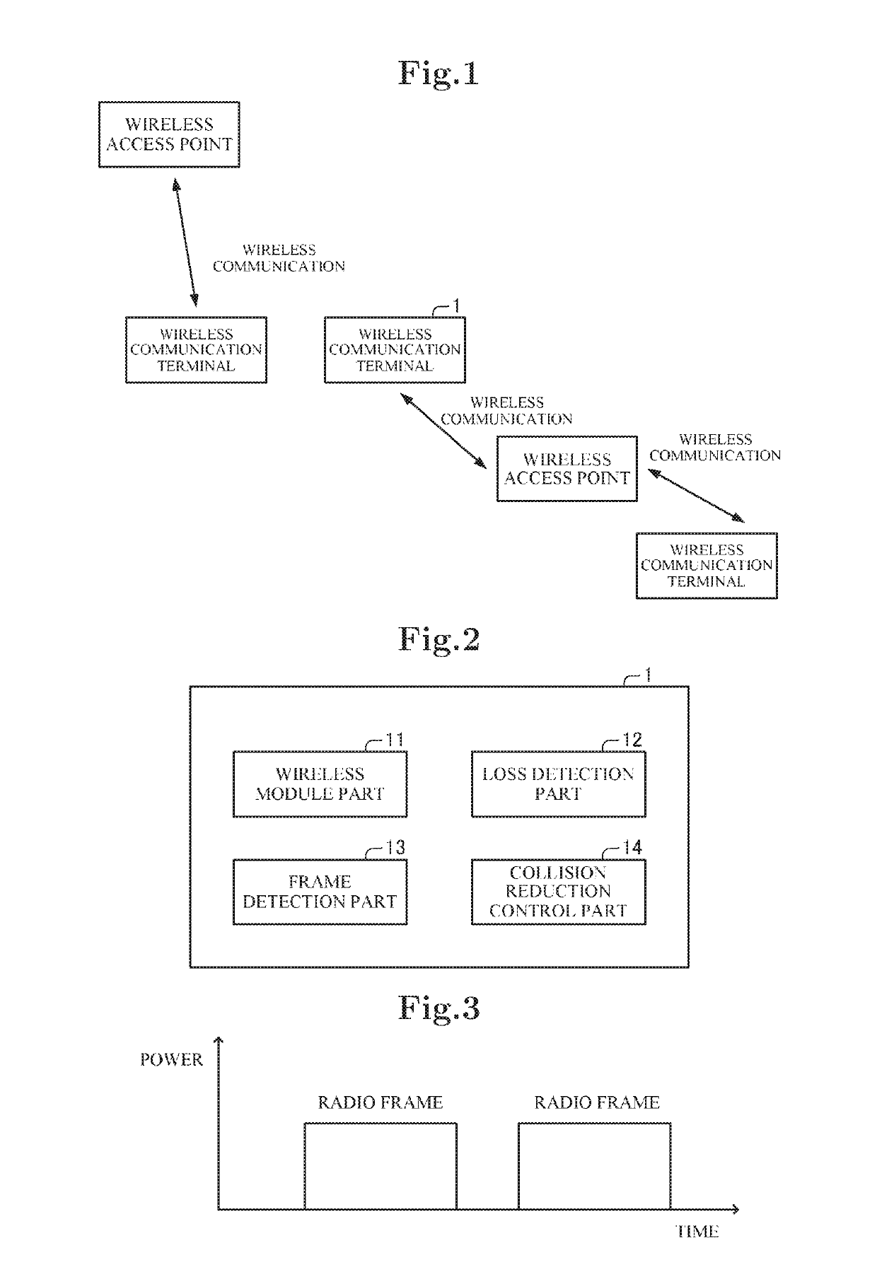
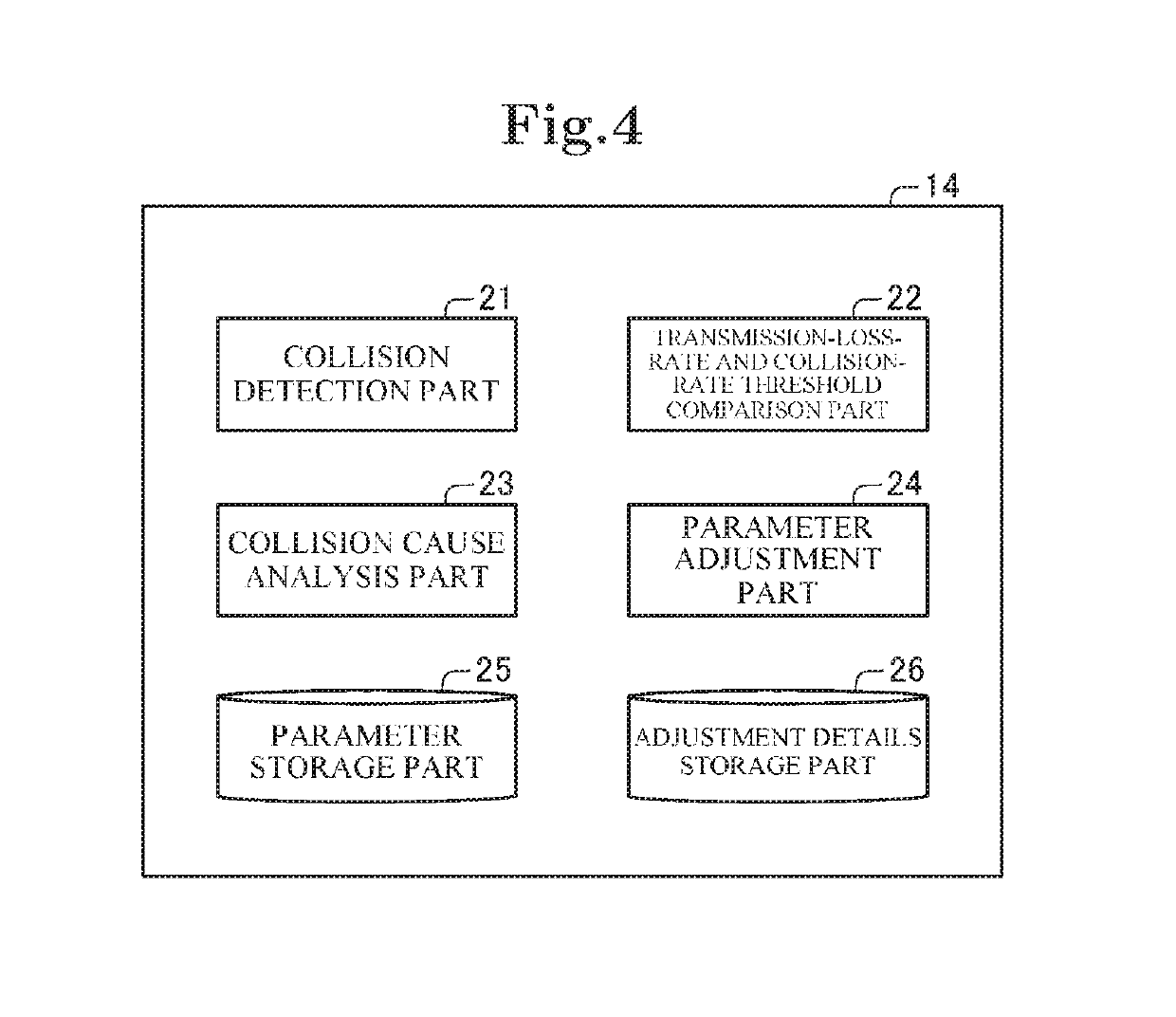
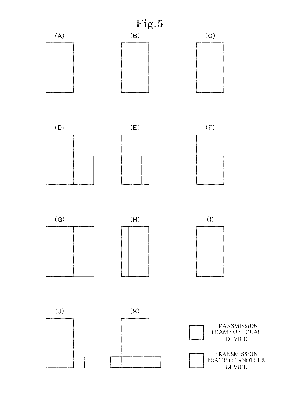
[0086]Referring to FIG. 1, a wireless communication terminal 1 in a first exemplary embodiment of the present invention is a terminal which performs wireless communication with another wireless communication terminal, a wireless access point, and the like. As described later, the wireless communication terminal 1 in this exemplary embodiment is configured to be able to detect collision between a radio frame signal transmitted by the wireless communication terminal 1 and a radio frame signal transmitted by another device. Moreover, the wireless communication terminal 1 in this exemplary embodiment is configured to detect the status of collision (a collision status) of wireless frame signals. Furthermore, the wireless communication terminal 1 in this exemplary embodiment is configured to change a parameter depending on a detected collision status.

[0087]Referring to FIG. 2, the wireless communication terminal 1 in this exemplary embodiment has a wireless module part 11, a loss detectio...

second exemplary embodiment

[0152]Next, a second exemplary embodiment of the present invention will be described referring to the drawings. In the second exemplary embodiment, a wireless communication terminal 3 which can estimate the number of terminals around itself will be described as an application of the first exemplary embodiment. The wireless communication terminal 3 has the same components as the wireless communication terminal 1 described in the first exemplary embodiment. Therefore, in this exemplary embodiment, a component characteristic of the second exemplary embodiment will be described. In the drawings to be described below, the same component as the already described component will be denoted by the same reference numeral.

[0153]Referring to FIG. 20, the wireless communication terminal 3 has the wireless module part 11, the loss detection part 12, the frame detection part 13, and a collision reduction control part 34. Moreover, referring to FIG. 21, the collision reduction control part 34 has f...

third exemplary embodiment

[0167]Next, a third exemplary embodiment of the present invention will be described referring to the drawings. In the third exemplary embodiment, a wireless communication terminal 4 configured to be able to also execute channel shift as one of the changes of parameters according to collision statuses will be described. The wireless communication terminal 4 in this exemplary embodiment is configured to estimate the number of terminals around itself. Moreover, the wireless communication terminal 4 in this exemplary embodiment is configured to execute channel shift when the estimated number of terminals exceeds a predetermined shift threshold.

[0168]Referring to FIG. 22, the wireless communication terminal 4 in this exemplary embodiment has the wireless module part 11, the loss detection part 12, the frame detection part 13, the collision reduction control part 34, and a channel shift determination part 45.

[0169]As described before, the collision reduction control part 34 is configured ...


PUM


Abstract

A wireless communication terminal has: a wireless module part which transmits a radio frame signal; a transmission loss information detection part which detects transmission loss information representing whether or not the radio frame signal transmitted by the wireless module part has reached a transmission destination; a collision information detection part which detects collision information representing an aspect of collision between the radio frame signal transmitted by the wireless module part and another radio frame signal; and a transmission control part which controls a transmission process executed by the wireless module part, on a basis of the transmission loss information and the collision information.

Description

CROSS-REFERENCE TO RELATED APPLICATIONS[0001]This application is a national stage application of International Application No. PCT / JP2014 / 004188 entitled “Wireless Communication Terminal,” filed on Aug. 14, 2014, which claims priority to Japanese Patent Application No. 2014-026463, filed on Feb. 14, 2014, the disclosures of each which are hereby incorporated by reference in their entirety.TECHNICAL FIELD[0002]The present invention relates to a wireless communication terminal, a wireless communication method, and a program. In particular, the present invention relates to a wireless communication terminal detecting the aspect of collision of transmitted radio frames and executing given control, a wireless communication method, and a program.BACKGROUND ART[0003]In recent years, communication terminals including smartphones, tablets and wireless access points have increased. As communication terminals performing wireless communication become popular, frequency resources are shared by ma...

Claims


Application Information

Patent Timeline
Patent Type & Authority Patents(United States)
IPC IPC(8): H04W74/08H04L12/413
CPCH04L12/413H04W74/0825
Inventor BABA, YUKIMATSUMOTOSHAO, PENG
Owner NEC COMM SYST
Learn More