
Gate drive IC with adaptive operating mode

a technology of operating mode and drive, applied in the direction of electric variable regulation, process and machine control, instruments, etc., can solve the problems of flickering of the lighting output of the load, no available solution for avoiding random pulse mode,

Active Publication Date: 2019-03-26
UNIVERSAL LIGHTING TECHNOLOGIES
View PDF4 Cites 7 Cited by
  • Summary
  • Abstract
  • Description
  • Claims
  • Application Information

AI Technical Summary

Benefits of technology

The patent describes a modification to a conventional gate drive integrated circuit to create a new controller that can smoothly transition from critical mode to discontinuous mode and avoid the random pulse mode that causes flickering of lighting output. The new controller can adjust the off-time of the gate drive signals depending on the internal error voltage. This helps to improve the efficiency of the circuit and reduce energy consumption.

Problems solved by technology

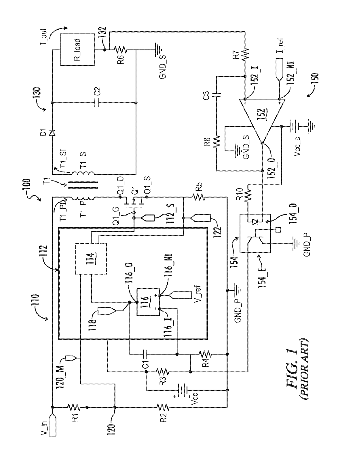
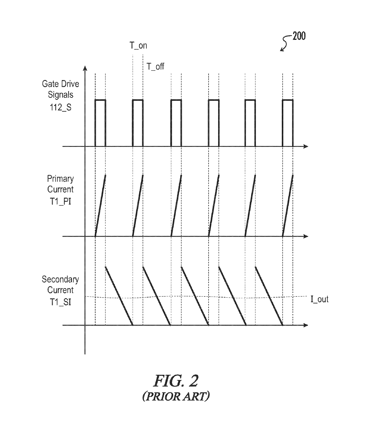
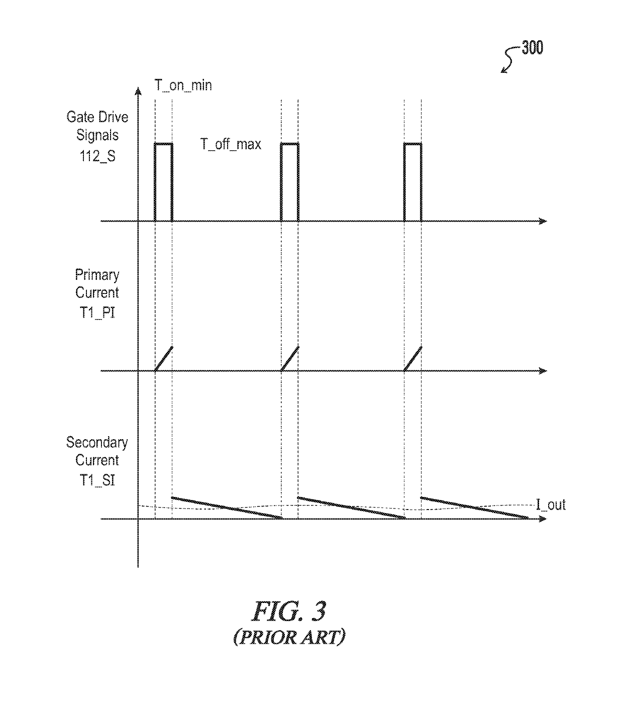
Since the gate drive signals 112_S are randomly pulsing, the output current I_out and load voltage V_load will be randomly changing, which will result in an annoying flickering of the lighting output from the load.
There are no available solutions for avoiding the random pulse mode when the gate drive integrated circuit is operated at its limits, or when the output current or equivalent resistance of the load are decreased below their discontinuous values.

Method used


Image

  • Gate drive IC with adaptive operating mode
  • Gate drive IC with adaptive operating mode
  • Gate drive IC with adaptive operating mode

Examples


Embodiment Construction

[0049]While the making and using of various embodiments of the present invention are discussed in detail below, it should be appreciated that the present invention provides many applicable inventive concepts that can be embodied in a wide variety of specific contexts. The specific embodiments discussed herein are merely illustrative of specific ways to make and use the invention and do not delimit the scope of the invention. Where the various figures may describe embodiments sharing various common elements and features with other embodiments, similar elements and features are given the same or similar reference numerals and redundant description thereof may be omitted below.

[0050]Referring generally to FIG. 5, exemplary light emitting diode (LED) drivers, gate drive integrated circuits, and methods to enable a smooth transition from a first operating mode to a second operating mode of a gate drive integrated circuit are now illustrated in greater detail. An exemplary power converter...


PUM


Abstract

An LED driver is provided having a gate drive integrated circuit with an adaptive operating mode which operates between a first operating mode and a second operating mode. The gate drive integrated circuit is designed to primarily operate in the first operating mode which includes a predetermined minimum on-time and a predetermined maximum off-time for enabling and disabling gate drive signals to a switch, respectively. The second operating mode begins at the minimum on-time and the maximum off-time. The LED driver further includes a controller configured to monitor an on-time and an off-time of the gate drive signals. The controller is further configured responsive to the second operating mode to fix the on-time equal to the predetermined minimum on-time and to continually adjust the off-time greater than or equal to the maximum off-time.

Description

[0001]A portion of the disclosure of this patent document contains material that is subject to copyright protection. The copyright owner has no objection to the reproduction of the patent document or the patent disclosure, as it appears in the U.S. Patent and Trademark Office patent file or records, but otherwise reserves all copyright rights whatsoever.CROSS-REFERENCES TO RELATED APPLICATIONS[0002]This application claims benefit of the following patent application(s) which is / are hereby incorporated by reference: U.S. Provisional Patent Application No. 62 / 553,200 filed Sep. 1, 2017, entitled “Gate Drive IC with Adaptive Operating Mode.”FIELD OF THE INVENTION[0003]The present disclosure relates generally to power supplies that provide a constant DC output current to a load, such as, for example, light-emitting diodes. More particularly, the present disclosure relates to a lighting device including adaptive gate driving circuitry which automatically switches between operating modes t...

Claims


Application Information

Patent Timeline
Patent Type & Authority Patents(United States)
IPC IPC(8): H02M3/335H02M1/088H02M1/44
CPCH02M3/33569H02M1/088H02M1/44H02M3/33523Y02B20/30Y02B70/10H05B45/382H02M1/0032
Inventor XIONG, WEIBERRY, TRAVIS L.DAVIS, KEITH
Owner UNIVERSAL LIGHTING TECHNOLOGIES
Learn More