
Systems and methods for prosthetic wrist rotation

Active Publication Date: 2019-03-28
TOUCH BIONICS
View PDF0 Cites 17 Cited by
  • Summary
  • Abstract
  • Description
  • Claims
  • Application Information

AI Technical Summary

Benefits of technology

The patent describes a prosthetic wrist and associated methods that can be used with a prosthetic hand. The wrist can rotate and has features to prevent separation from the socket. The wrist includes torque control features to prevent premature separation of the hand. The method of securing the wrist with the socket involves attaching a body of the wrist with a prosthetic socket and expanding the coupling outward to better secure the wrist. The method also includes rotating the rotatable shaft to cause the shaft to move axially and expand the coupling. The prosthetic hand and wrist system described can command a grip and the wrist will rotate responsively and in an efficient manner to simulate natural hand and wrist movement. The system also includes an inertial measurement unit and a memory with instructions to control the actuator module to transmit rotation to the prosthetic hand. Overall, this patent provides a more responsive and efficient upper limb prosthetic system for amputees.

Problems solved by technology

However, existing solutions have deficient wrist control.
For instance, existing solutions cause responsive delay with wrist rotation that detracts from more closely mimicking the functionality of a natural wrist.
As another example, existing solutions insufficiently synchronize wrist movement with other prosthetic movements, such as grip formation with a prosthetic hand and / or rotation of a prosthetic arm, which detracts from more closely mimicking the functionality of a natural limb.
Further, existing solutions have deficient connection and disconnection features for attaching and removing the prosthetics from a user.

Method used


Image

  • Systems and methods for prosthetic wrist rotation
  • Systems and methods for prosthetic wrist rotation
  • Systems and methods for prosthetic wrist rotation

Examples


Embodiment Construction

,” one will understand how the features of the embodiments described herein provide advantages over existing systems, devices and methods.

[0006]The following disclosure describes non-limiting examples of some embodiments. For instance, other embodiments of the disclosed systems and methods may or may not include the features described herein. Moreover, disclosed advantages and benefits can apply only to certain embodiments of the invention and should not be used to limit the disclosure.

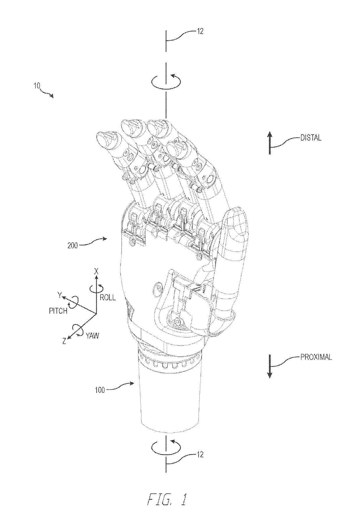
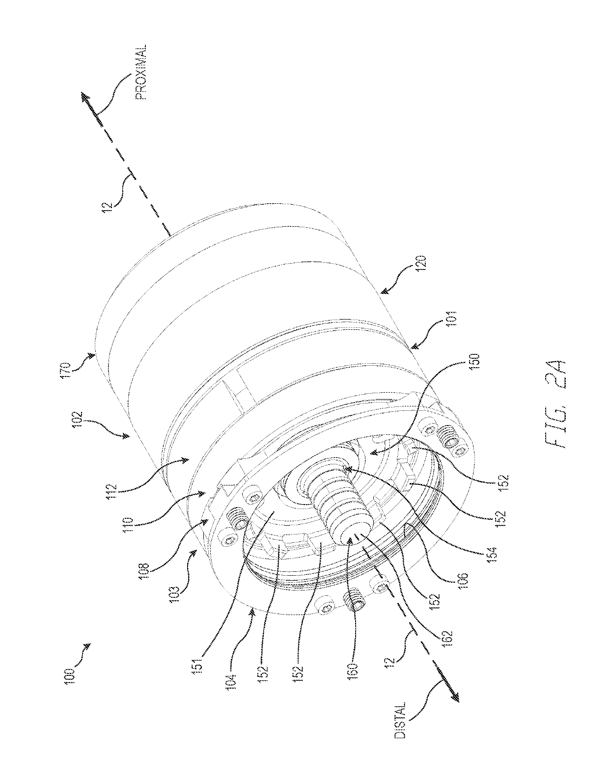
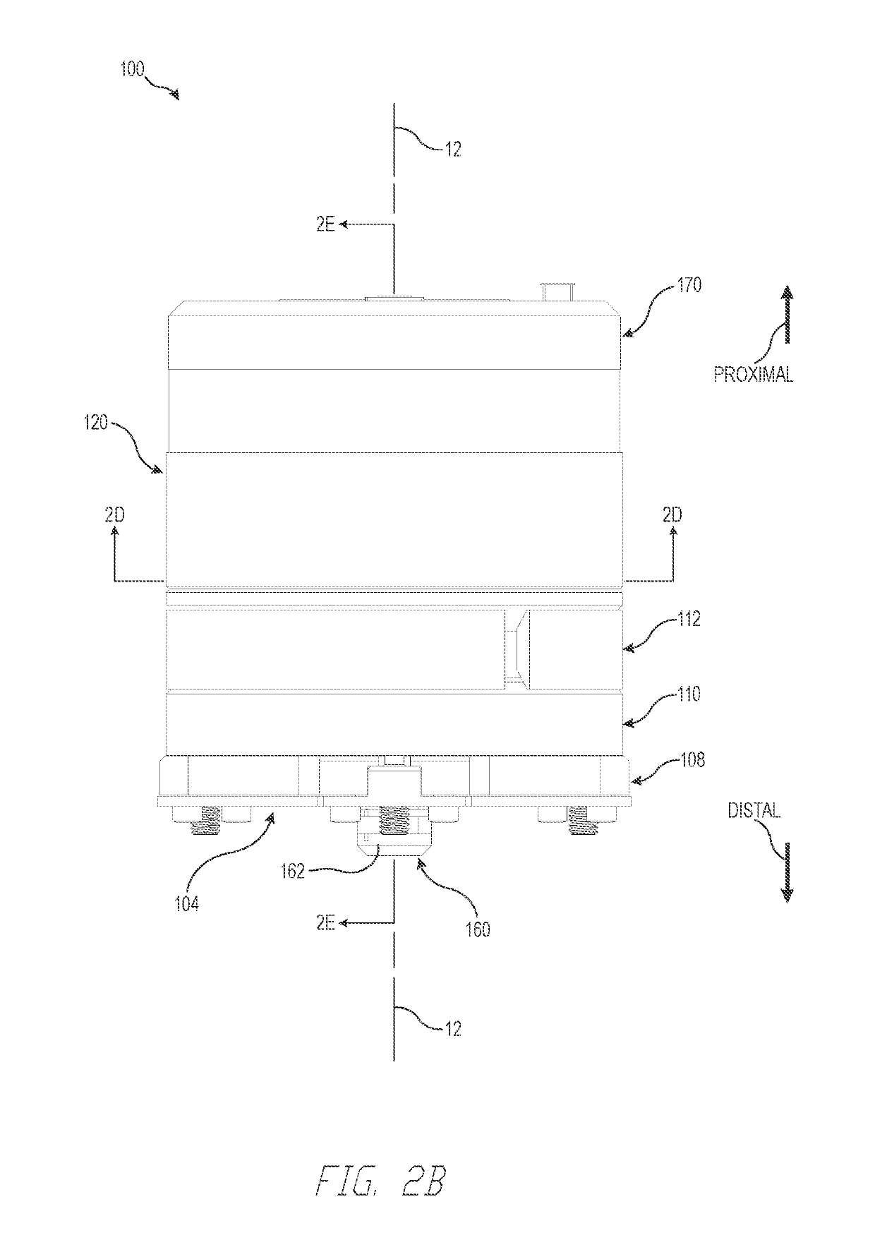
[0007]Features for a prosthetic wrist and associated methods are described. The wrist couples with a prosthetic socket and a prosthetic hand. The wrist may rotate the hand. The wrist includes features to prevent or mitigate undesirable separation of the wrist from the socket. The wrist may have an expanding coupling, such as an expanding ring, to better secure the wrist with the socket. An actuator may cause the coupling to expand outward to prevent or mitigate undesirable separation of the wrist from...


PUM


Abstract

Features for a prosthetic wrist and associated methods are described. The wrist couples with a prosthetic socket and a prosthetic hand. The wrist may rotate the hand. The wrist includes features to prevent or mitigate undesirable separation of the wrist from the socket. The wrist may have an expanding coupling, such as an expanding ring, to better secure the wrist with the socket. An actuator may cause the coupling to expand outward to prevent or mitigate undesirable separation of the wrist from the socket. Alternatively or in addition, the wrist may include torque control features to prevent undesirable or premature separation of the hand from the wrist, for example when using a “quick wrist disconnect” (QWD) apparatus. A torque control method may tailor or limit multiple torques to be applied by the wrist to the hand based on operational requirements and phases, such as anticipated torque loads and operational timing.

Description

INCORPORATION BY REFERENCE TO ANY PRIORITY APPLICATIONS[0001]Any and all applications for which a foreign or domestic priority claim is identified in the Application Data Sheet as filed with the present application are hereby incorporated by reference under 37 CFR 1.57.[0002]This application is a continuation in part of U.S. patent application Ser. No. 15 / 341,939, filed Nov. 2, 2016, entitled SYSTEMS AND METHODS FOR PROSTHETIC WRIST ROTATION, which claims the benefit of U.S. Provisional Patent Application No. 62 / 382,919, filed Sep. 2, 2016, entitled SYSTEMS AND METHODS FOR PROSTHETIC WRIST ROTATION, the disclosure of each of which is incorporated herein by reference in its entirety for all purposes.BACKGROUNDField[0003]Described herein are features related to prosthetics, for example a prosthetic hand and wrist system and associated methods.Description of the Related Art[0004]Hand and arm amputees benefit greatly from prosthetic replacements. Prosthetic hands, wrists, and / or arms re...

Claims


Application Information

Patent Timeline
IPC IPC(8): A61F2/58A61F2/72A61F2/76
CPCA61F2/585A61F2/586A61F2/72A61F2/76A61F2002/6854A61F2002/5043B25J15/0009A61F2002/6872A61F2002/701A61F2002/5072A61F2002/6836A61F2/70A61F2002/707A61F2002/704A61F2002/763A61F2002/7625A61F2002/5083A61F2/54A61F2002/587A61F2002/5093A61F2002/705A61F2002/764
Inventor GILL, HUGHRIVERA, RODRIGO MERCADER
Owner TOUCH BIONICS
Learn More