
Wireless power transfer system and driving method thereof

a technology of power transmission system and driving method, which is applied in the direction of emergency protective arrangements, transportation and packaging, and arrangements responsive to excess voltage, can solve the problems of increasing size and power consumption, and achieve the effect of improving consumption power and minimizing additional constituent elements

Active Publication Date: 2019-03-19
SEMICON COMPONENTS IND LLC
View PDF13 Cites 1 Cited by
  • Summary
  • Abstract
  • Description
  • Claims
  • Application Information

AI Technical Summary

Benefits of technology

The present invention aims to provide a wireless power transmission system that can reduce additional elements and increase power consumption efficiency. The invention's driving method can also improve this system's performance.

Problems solved by technology

Such addition of constituent elements may cause increase in size and power consumption.

Method used


Image

  • Wireless power transfer system and driving method thereof
  • Wireless power transfer system and driving method thereof
  • Wireless power transfer system and driving method thereof

Examples


Embodiment Construction

[0026]In the following detailed description, only certain exemplary embodiments of the present invention have been shown and described, simply by way of illustration. As those skilled in the art would realize, the described embodiments may be modified in various different ways, all without departing from the spirit or scope of the present invention. Accordingly, the drawings and description are to be regarded as illustrative in nature and not restrictive. Like reference numerals designate like elements throughout the specification.

[0027]Throughout this specification and the claims that follow, when it is described that an element is “coupled” to another element, the element may be “directly coupled” to the other element or “electrically coupled” to the other element through a third element. In addition, unless explicitly described to the contrary, the word “comprise” and variations such as “comprises” or “comprising”, will be understood to imply the inclusion of stated elements but ...


PUM


Abstract

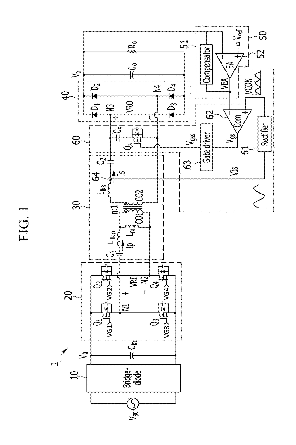
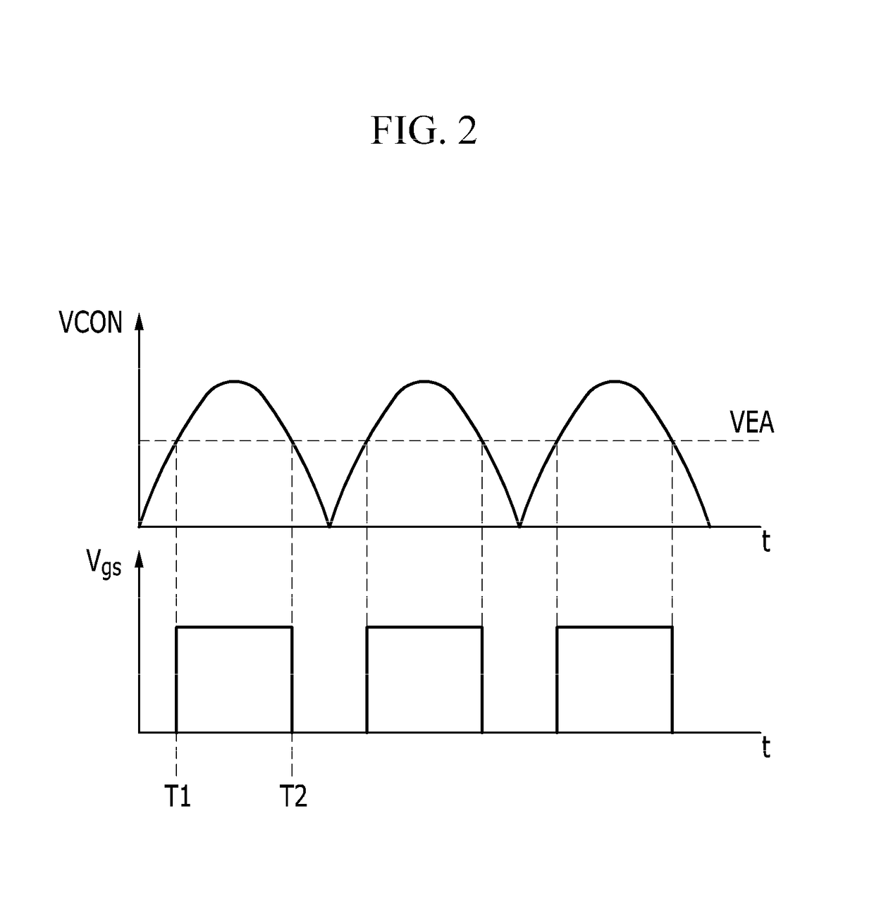
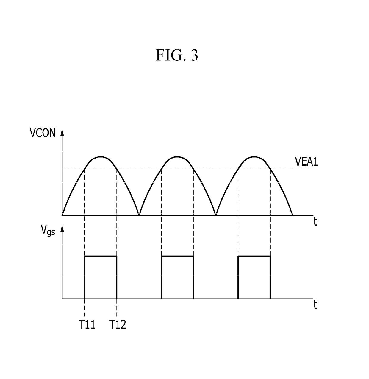
A wireless power transmission system according to an exemplary embodiment of the present invention transmits power from a primary side to a secondary side, and includes: a secondary coil provided at the secondary side; a capacitor and a control switch electrically coupled in series between lateral ends of the secondary coil; and a regulation controller controlling a switching operation of the control switch according to a result of comparison between a control signal synchronized by a frequency at the primary side and a feedback signal corresponding to an output of the wireless power transmission system.

Description

CROSS-REFERENCE TO RELATED APPLICATION[0001]This application claims priority to and the benefit of U.S. Patent Application No. 61 / 882,705 filed in the USPTO on Sep. 26, 2013, and priority to and the benefit of Korean Patent Application No. 10-2014-0121346, filed with the Korean Intellectual Property Office on Sep. 12, 2014, the entire contents of which are incorporated herein by reference.BACKGROUND OF THE INVENTION[0002](a) Field of the Invention[0003]An exemplary embodiment of the present invention relates to a wireless power transmission system and a driving method thereof.[0004](b) Description of the Related Art[0005]A wireless power transmission system generates an AC electromagnetic field at a primary side using a conductive coil, and a second conductive coil at a secondary side receives power from the AC electromagnetic field generated at the primary side.[0006]A pre-regulator or a post-regulator may be provided to control output of the wireless power transmission system.[000...

Claims


Application Information

Patent Timeline
Patent Type & Authority Patents(United States)
IPC IPC(8): H02J5/00H02J50/12H02J7/02
CPCH02J50/12H02J7/025H02J5/005H02H3/20H02H9/041
Inventor MOON, SANGCHEOLKOO, GWANBON
Owner SEMICON COMPONENTS IND LLC
Learn More