
Leg rest apparatus

a leg rest and apparatus technology, applied in the direction of chairs, vehicles, vehicle components, etc., can solve the problem that the automatic link device is applied to limited high-grade vehicles, and achieve the effect of reducing the number of springs, reducing the number of components and a weight of the apparatus, and simplifying the link motion

Active Publication Date: 2019-03-19
HYUNDAI MOTOR CO LTD +1
View PDF17 Cites 4 Cited by
  • Summary
  • Abstract
  • Description
  • Claims
  • Application Information

AI Technical Summary

Benefits of technology

[0006]The present invention provides a leg rest apparatus, which may be used manually as well as automatically (e.g., by additionally mounting a motor or the like), enables link motion to be simplified (e.g., to four-axis articulated link motion) to reduce the number of components and improves support quality by allowing a leg rest panel to be moved further downward, when the leg rest panel is deployed.
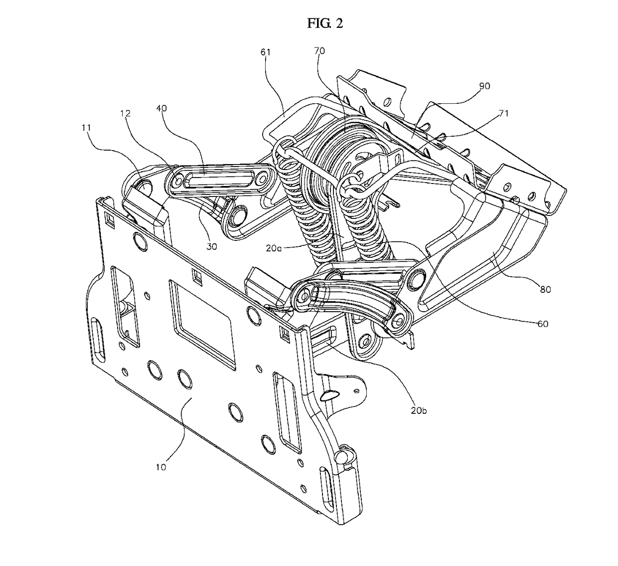
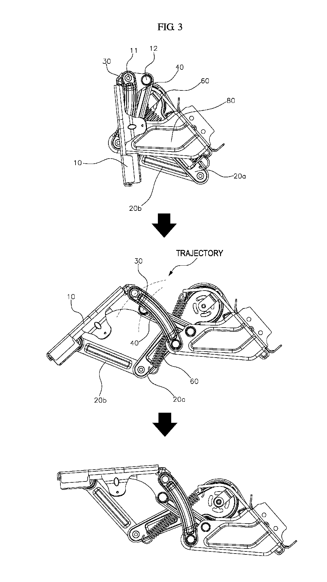
[0010]According to another exemplary embodiment the leg rest panel may be configured to rotate by a difference in trajectory between the front guide link and the rear guide link at the same time when the leg rest panel is adjusted forward by the lift link, the link motion may be simplified compared to the link motion in the related art structure. Accordingly, the number of components and a weight of the apparatus may be reduced.
[0011]In an exemplary embodiment, since the centerline α in the longitudinal direction of the spring and the centerline β in the longitudinal direction of the rear lift link may be disposed to form the included angle θ of 0° or greater to extend the spring beyond the dead point (e.g., extends maximally) when the leg rest panel is adjusted from the stored position to the deployed position, the spring may be configured to provide an elastic force to maintain the position of the leg rest panel when the leg rest panel is adjusted to the stored position or the deployed position. Therefore, when the single spring is configured to provide elastic force at different positions (e.g., stored position or deployed position), the reduce the number of springs may be reduced (e.g., compared to a structure in the related art).
[0012]Operating force of the leg rest may be adjusted to meet the specifications by adjusting the positions of the first coupling portion and the second coupling portion and / or changing the lengths of the front guide link and the rear guide link (e.g., increasing or decreasing a difference in trajectory). Additionally, since the deformation amount of the spring for each movement distance of the leg rest panel may be reduced (e.g., since the link motion is simplified compared to the link motion in the related art), the operating force may be decreased. In particular, a portion where seated passenger's legs come into direct contact with the leg rest panel may be further downward compared to the structure in the related art (see FIG. 5), to improve support quality.

Problems solved by technology

However, due to a high cost the automatic link device is applied only to limited high-grade vehicles.

Method used


Image

  • Leg rest apparatus
  • Leg rest apparatus
  • Leg rest apparatus

Examples


Embodiment Construction

[0020]Hereinafter, the present invention will be described in detail with reference to the accompanying drawings so that those skilled in the technical field to which the present invention pertains may easily carry out the present invention. However, the present invention may be implemented in various different ways, and is not limited to the exemplary embodiment described herein. On the contrary, the invention is intended to cover not only the exemplary embodiments, but also various alternatives, modifications, equivalents and other embodiments, which may be included within the spirit and scope of the invention as defined by the appended claims. Wherever possible, the same reference numbers will be used throughout the drawings to refer to the same or like parts. A part irrelevant to the description will be omitted to clearly describe the present invention, and the same or similar constituent elements will be designated by the same reference numerals throughout the specification.

[00...


PUM


Abstract

A leg rest apparatus is provided. A leg rest panel is configured to be adjusted between a deployed position and a stored position. The apparatus includes a lift link that articulates a rear end and a front end rotatably coupled to the seat and the leg rest panel, respectively. A link base with a rear end fixed to the seat is separated from the lift link and a front end is disposed toward a front side of the seat. A front guide link with a front end and a rear end is rotatably connected to a first coupling portion of the leg rest panel and the link base, respectively. A rear guide link with a length less than the front guide link and a front end and a rear end rotatably connected to a second coupling portion separated from the first coupling portion and the link base, respectively.

Description

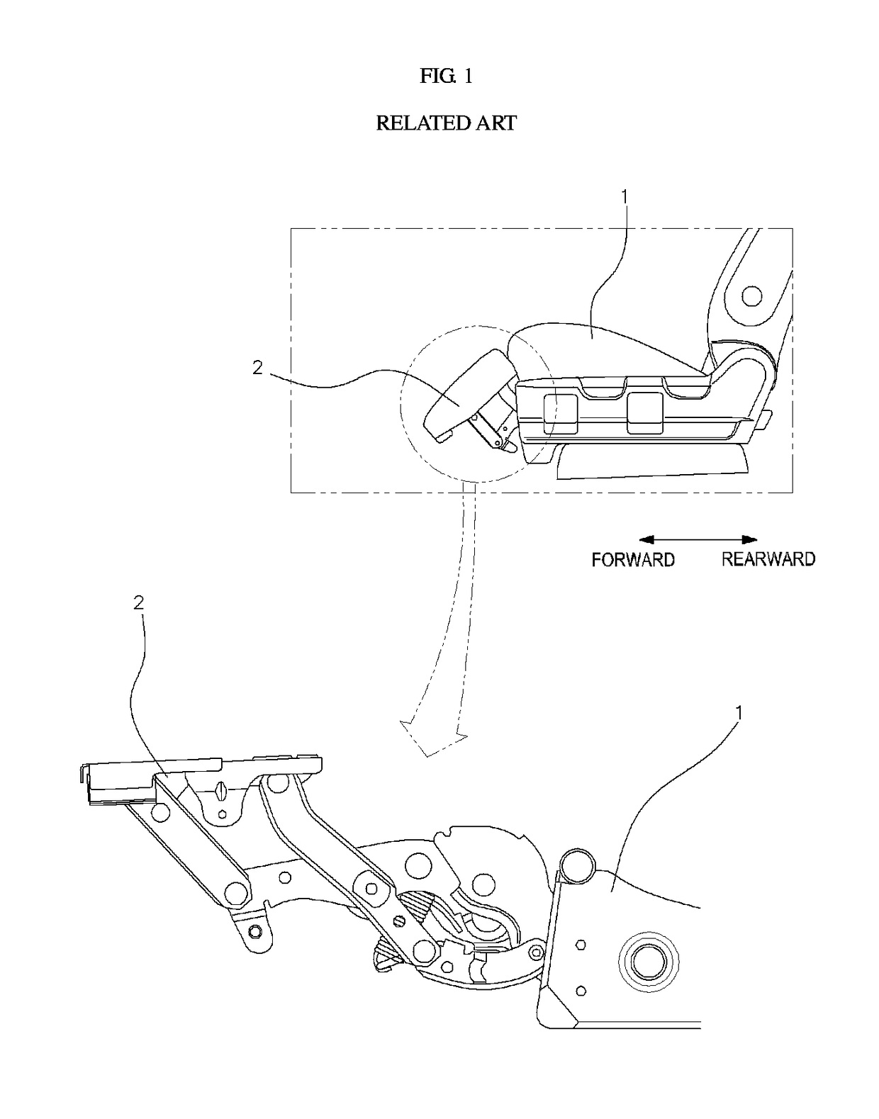
CROSS-REFERENCE TO RELATED APPLICATIONS[0001]This application claims priority under 35 U.S.C. § 119 to Korean Patent Application No. 10-2016-0056566, filed on May 9, 2016, in the Korean Intellectual Property Office, the disclosure of which is incorporated herein by reference in its entirety.BACKGROUND1. Field of the Invention[0002]The present invention relates to a leg rest apparatus (e.g., structure of a leg rest) mounted at a front lower side of a seat of a vehicle and more particularly, to a leg rest that reduces the weight of the apparatus by reducing the number of components performing link motion.2. Description of the Related Art[0003]A leg rest apparatus for a vehicle is mounted at a lower side of a vehicle seat (e.g., a rear seat at a rear side), and supports seated passengers calves when the seated passengers calves are placed on the leg rest, to improve the passenger's comfort. The leg rest for a vehicle has a leg rest panel 2 coupled to a link device to adjust the leg res...

Claims


Application Information

Patent Timeline
Patent Type & Authority Patents(United States)
IPC IPC(8): B60N2/90
CPCB60N2/995A47C7/5068
Inventor KIM, BONG-KUSUNG, YOUNG-BOKKIM, SANG-HO
Owner HYUNDAI MOTOR CO LTD
Learn More