
Fluid delivery system for collected rainwater

Active Publication Date: 2019-03-19
RAINFLEX
View PDF9 Cites 13 Cited by
  • Summary
  • Abstract
  • Description
  • Claims
  • Application Information

AI Technical Summary

Benefits of technology

The fluid delivery system described in this patent is a device that uses pressurized fluids to distribute the fluids into the environment. The system includes a mixing chamber that combines the pressurized fluids with source fluids using Bernoulli principles. The system also has a discharge aperture for discharging the fluids. The system can be used in a variety of applications such as for fire extinguishment or for distributing fluids in a cooling system. The technical effects of the system include improved distribution of fluids and increased efficiency of the process.

Problems solved by technology

Efforts to reduce water consumption have had limited success.
Limited water resources have had an adverse impact on the ability of homeowners to water their lawns and gardens.
Furthermore, governments and municipalities have limited the use of irrigation and lawn watering in times of drought and limited water supply.
This is problematic in times of drought as homeowners may not be allowed to water their lawns that may already be suffering from the drought conditions.
Repair of lawns that have suffered from drought conditions is expensive.
Furthermore, drought-stricken lawns are unsightly and may impact the land value of a homeowner.
However, rainfall is unpredictable as far as occurrence and amounts.
However, this device may not be aesthetically pleasing or functional.
Other devices may not be easily installed upon a gutter assembly.
These devices may also clog easily or may have a debris filter that must be cleaned to function properly.
Another difficulty presented by existing rainwater collection systems is that the storage tank must be placed under the existing downspout which makes the tank conspicuous and difficult to conceal.
Still another disadvantage of existing systems is that those systems rely on gravity for evacuation of the collected water.
For this reason, the collection point in which water is collected within the gutter assembly of certain systems is often raised off of the ground to increase pressure, thus making it even more difficult to conceal.

Method used


Image

  • Fluid delivery system for collected rainwater
  • Fluid delivery system for collected rainwater
  • Fluid delivery system for collected rainwater

Examples


Embodiment Construction

[0038]These descriptions are presented with sufficient details to provide an understanding of one or more particular embodiments of broader inventive subject matters. These descriptions expound upon and exemplify particular features of those particular embodiments without limiting the inventive subject matters to the explicitly described embodiments and features. Considerations in view of these descriptions will likely give rise to additional and similar embodiments and features without departing from the scope of the inventive subject matters. Although the term “step” may be expressly used or implied relating to features of processes or methods, no implication is made of any particular order or sequence among such expressed or implied steps unless an order or sequence is explicitly stated.

[0039]Any dimensions expressed or implied in the drawings and these descriptions are provided for exemplary purposes. Thus, not all embodiments within the scope of the drawings and these descripti...


PUM


Abstract

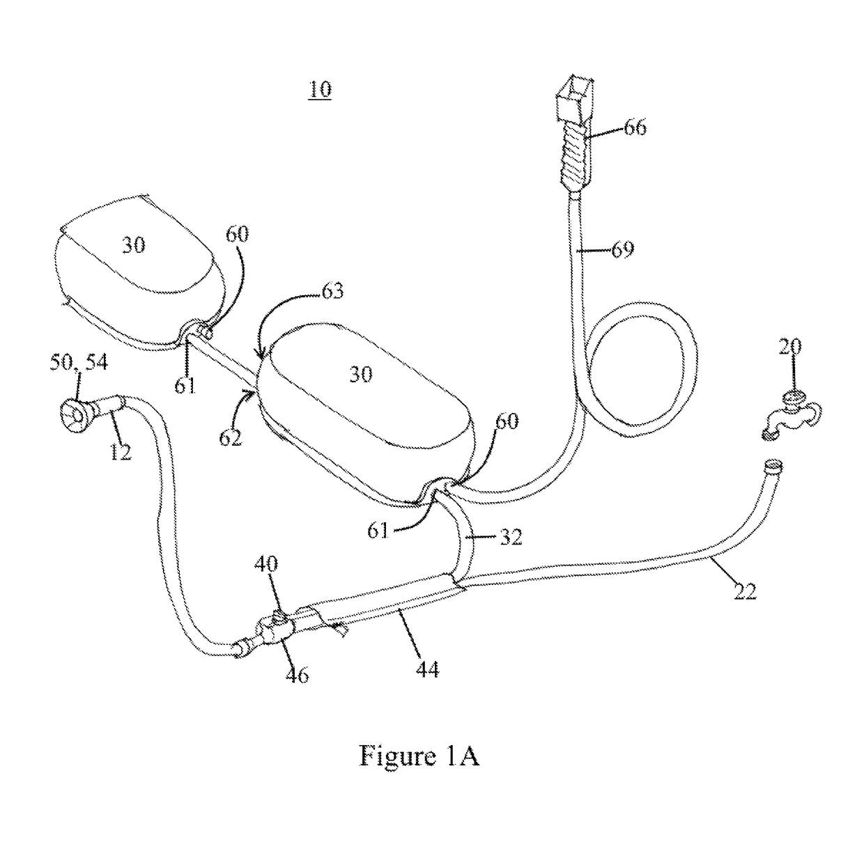
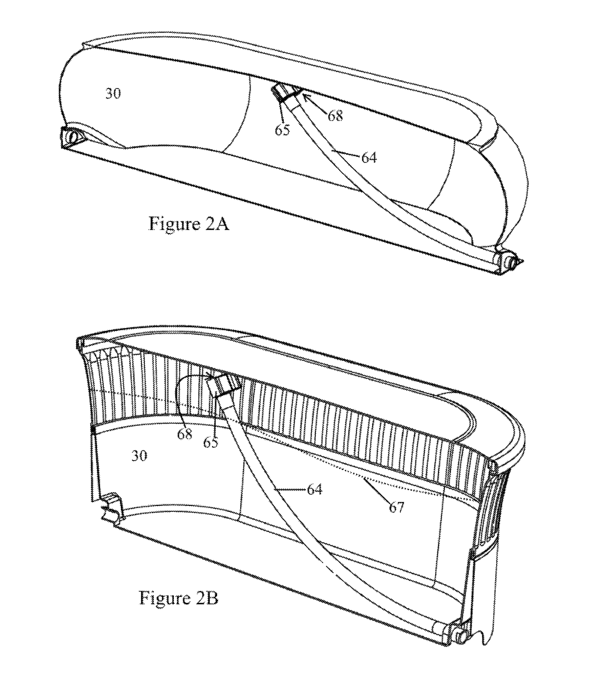
A fluid delivery system utilizes Bernoulli pressure differentials and kinetic forces is provided. The system includes a pressurized channel in fluid communication with a flexible pressurized line for translating pressurized fluids to a mixing chamber. The mixing chamber is also in fluid communication with a source channel receiving fluids from a flexible source line. The mixing chamber is configured for entraining the source fluids with the pressurized fluids 26 using Bernoulli principles. Kinetic valves may be used in conjunction with, or in lieu of, the Bernoulli siphoning.

Description

CROSS-REFERENCE TO RELATED APPLICATIONS[0001]This application is a non-provisional claiming the benefit of U.S. Provisional Application 62 / 066,319 filed Oct. 20, 2014, which is hereby incorporated by reference in its entirety.TECHNICAL FIELD[0002]The presently disclosed subject matter is directed towards a fluid delivery system having improved fluid delivery characteristics. Specifically, the fluid delivery system may be used to deliver collected rainwater efficiently using a second water source.BACKGROUND[0003]Water conservation has become increasingly important due to limited water resources amid rising populations and increased demand for water. Efforts to reduce water consumption have had limited success.[0004]Limited water resources have had an adverse impact on the ability of homeowners to water their lawns and gardens. Furthermore, governments and municipalities have limited the use of irrigation and lawn watering in times of drought and limited water supply. This is problema...

Claims


Application Information

Patent Timeline
IPC IPC(8): B05B15/70F15D1/06B05B7/04E03B3/02B05B3/02
CPCB05B15/70B05B7/0408F15D1/06B05B3/02E03B3/02B05B1/267B05B1/323B05B3/003B05B3/0468B05B3/0481B05B3/0486B05B3/06B05B7/1209B05B7/2443B05B7/2448B05B7/2454B05B7/2464B05B9/0413B05B15/622A01G25/00
Inventor FORREST, PAUL BRADLEY
Owner RAINFLEX
Learn More