Eureka AIR delivers breakthrough ideas for toughest innovation challenges, trusted by R&D personnel around the world.

Stage apparatus and microscope

a technology of stage apparatus and microscope, which is applied in the direction of microscopes, instruments, optics, etc., can solve the problems of distortion in the x and y directions of each member of the xy stage, and the difficulty of high-precision observation position management on the xy stage, so as to suppress the occurrence of distortion

Active Publication Date: 2019-03-05
CANON KK
View PDF24 Cites 0 Cited by
  • Summary
  • Abstract
  • Description
  • Claims
  • Application Information

AI Technical Summary

Benefits of technology

[0015]According to the present invention, it is possible to implement high-precision observation position management by suppressing the occurrence of distortion by the expansion / contraction of members caused by thermal expansion.

Problems solved by technology

This can cause distortion in each member of the XY stage in the X and Y directions.
The influence of distortion on a glass scale for observation position management of the XY stage can make it difficult to implement high-precision observation position management on the XY stage.

Method used


Image

  • Stage apparatus and microscope
  • Stage apparatus and microscope
  • Stage apparatus and microscope

Examples


first embodiment

[0038][First Embodiment]

[Arrangement of Observation Position Management Microscope System]

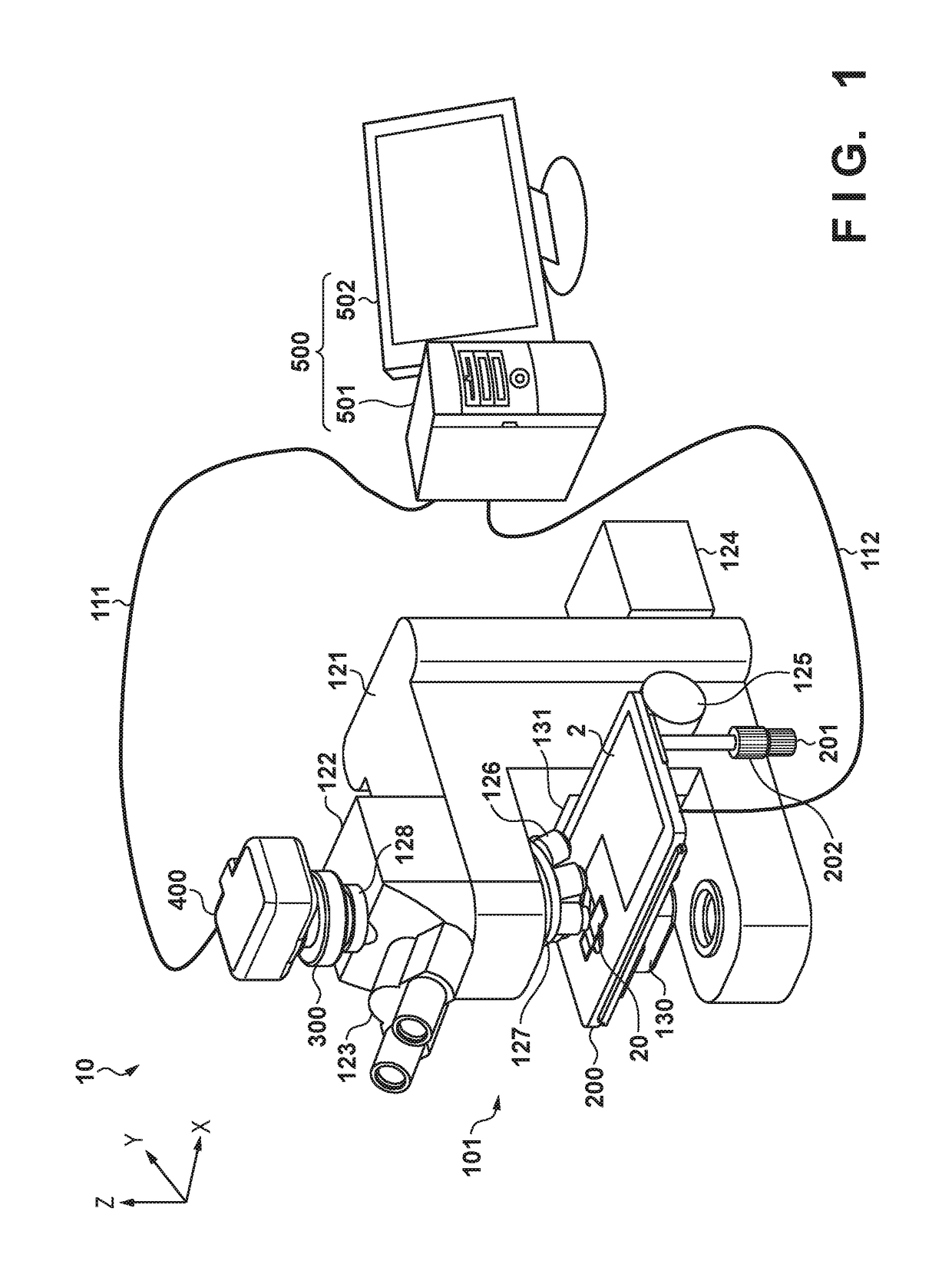
[0039]FIG. 1 is a perspective view showing the basic arrangement of an observation position management microscope system (to be referred to as a microscope system 10 hereinafter) according to this embodiment. The microscope system 10 includes a microscope body 101, a stage apparatus 200, an adapter unit 300 for camera attachment, a digital camera 400, and a control unit 500. The control unit 500 includes a controller 501 and a display 502.

[0040]A microscope base stand 121 as a component of the microscope body 101 is a robust body frame for the attachment of various types of structures of the microscope. An eyepiece microscope base stand 122 is fixed to the microscope base stand 121. An eyepiece lens barrel 123 (binoculars in this case) is connected to the eyepiece microscope base stand 122. A light source box 124 accommodates a light source for transmission observation (for example, a halogen l...

second embodiment

[0114][Second Embodiment]

[Arrangement of Stage Apparatus 200]

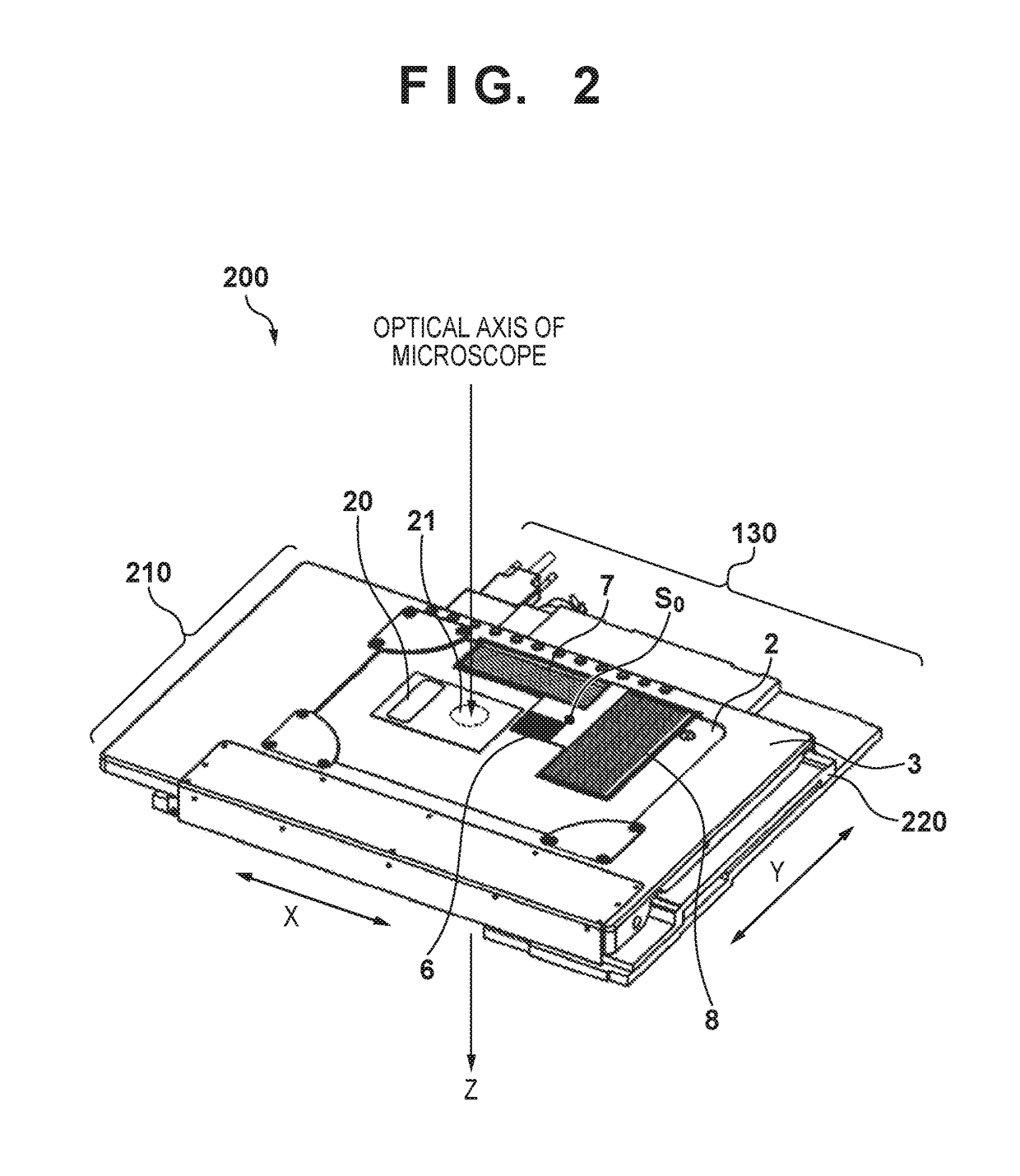
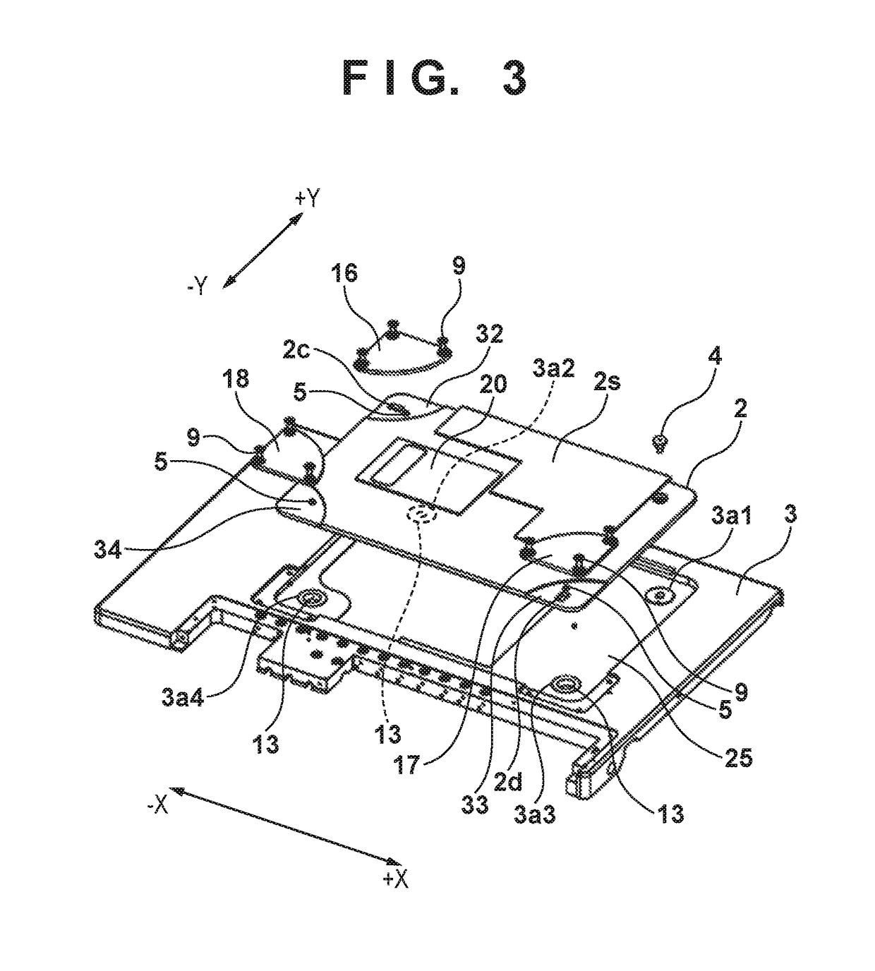
[0115]The arrangement of the stage apparatus 200 will be described with reference to FIG. 6. Referring to FIG. 6, the XY stage of the stage apparatus 200 is configured to be movable in the first direction (for example, the X direction) in a plane and the second direction (for example, the Y direction) intersecting with the first direction in an in-plane direction. The third direction (Z direction) intersecting with the first direction (X direction) and the second direction (Y direction) corresponds to the optical axis of the microscope. The stage apparatus 200 includes a plate-like X stage plate 3 (stage plate) having a spread in the first direction and the second direction intersecting with the first direction and an XY scale plate 2 (plate member) having a linear expansion coefficient different from that of the X stage plate 3 (stage plate).

[0116]In the following description, a moving mechanism in the first direction is ...


PUM


Abstract

A stage apparatus includes a plate-like stage plate having a spread in a first direction and a second direction intersecting with the first direction and a plate member having a linear expansion coefficient different from that of the stage plate. The stage apparatus includes: a first holding unit configured to hold the plate member on the stage plate; a second holding unit configured to hold the plate member on the stage plate, allow relative deformation caused between the stage plate and the plate member in the first direction, and constrain the relative deformation in the second direction; and a third holding unit configured to hold the plate member on the stage plate, constrain the deformation in the first direction, and allow the deformation in the second direction.

Description

BACKGROUND OF THE INVENTION[0001]Field of the Invention[0002]The present invention relates to a stage apparatus which moves while a slide is placed thereon and a microscope equipped with the stage apparatus.[0003]Description of the Related Art[0004]Recently, an optical microscope has been used by pathologists for pathological diagnosis as a means for implementing fine observation of a tissue segment of a lesion. When microscope examines, a slide glass on which an observation target is placed is placed on a stage for a microscope, and the stage is moved to locate the observation region immediately below an objective lens (observation visual field). When performing microscopic observation, it is necessary to move a measurement region by a very small dimension with high precision, as needed. In order to meet such a requirement, a stage apparatus for a microscope is formed from an XY stage so as to be capable of arbitrarily moving in two-dimensional directions and is required to impleme...

Claims


Application Information

Patent Timeline
Patent Type & Authority Patents(United States)
IPC IPC(8): G02B21/26G02B21/36
CPCG02B21/362G02B21/26
Inventor SAKAI, AKIHIRO
Owner CANON KK
Why Eureka
Eureka Blog
Learn More