
System and method for laser lysis

a laser lysis and laser lysis technology, applied in the field of cell analysis techniques, can solve the problems of difficult analysis of individual live cells, inability to capture lysate from individual cells in situ, and obscure valuable biological states

Active Publication Date: 2019-03-05
ARIZONA STATE UNIVERSITY
View PDF23 Cites 7 Cited by
  • Summary
  • Abstract
  • Description
  • Claims
  • Application Information

AI Technical Summary

Benefits of technology

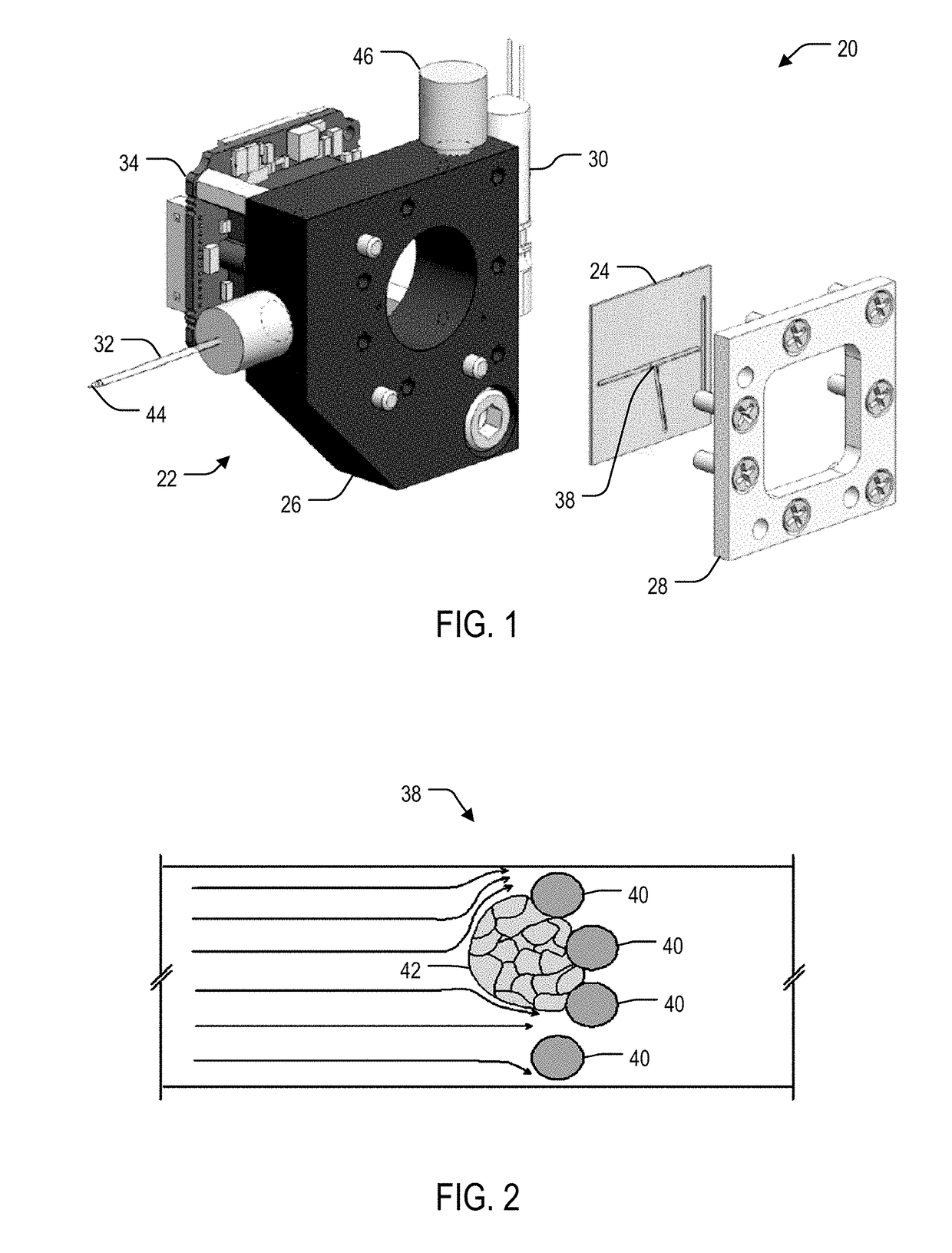
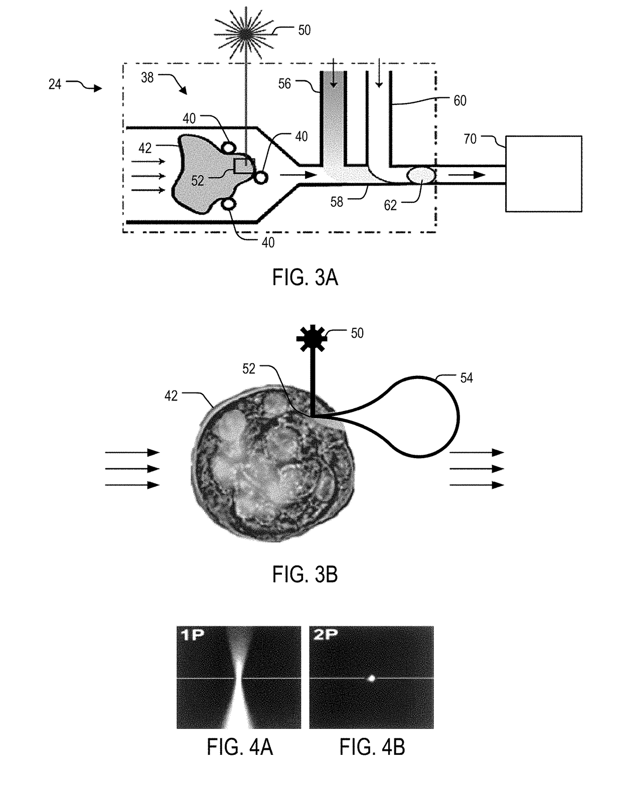
The present invention is a system and method for analyzing tissue at a single cell resolution using in situ laser lysis. The system includes a microfluidic chip with a cage for capturing tissue samples, a laser for irradiating a selected area of the tissue sample, and a downstream module for processing target molecules collected from the tissue sample. The laser lysis releases at least a portion of the cellular content from the tissue sample, which is then collected in the fluid channel and processed. This technology allows for more accurate and efficient analysis of tissue samples.

Problems solved by technology

However, such methodologies may require cells to be dissociated from their native environments and therefore, may obscure valuable biological states that are influenced by multicellular complexity in situ.
Current tools are not able to capture lysate from individual cells in situ, especially making it difficult to analyze the individual live cells given the short-lived nature of RNA, which can degrade on time scales of seconds to minutes, as well as the fast response time of the cellular gene-expression machinery on the order of minutes.
However, the size of the probe head resulted in a physical limitation with respect to accessing the target cells.
Moreover, the time required for cell lysis is relatively lengthy at around 1 minute.
Finally, harvesting a quantity of cells to acquire statistically significant results can be in excess of one hour, which may trigger cellular stress responses to the surrounding cells.

Method used


Image

  • System and method for laser lysis
  • System and method for laser lysis
  • System and method for laser lysis

Examples


examples

[0074]For optimization of SQUIRT-PCR, two-photon (2P) laser lysis was demonstrated to effectively lyse individual cells with sub-cellular resolution in a cluster without incurring visible damage to the neighboring cells. Various laser settings were tested to achieve sufficient lysis performance and mRNA harvest efficiency. Laser settings and optical configurations found to yield efficient lysis included 100×1.3 NA oil-immersion objective lens, fundamental laser wavelength of 800 nm with a pulse duration of 150-200 fs, 250 kHz repetition rate, 0.4 μJ pulse energy, and ˜1 s total exposure time. Moreover, targeting the nuclear membrane was discovered to easily generate micrometer-scale intracellular cavitation bubbles (Quinto-Su P A, et al. 2008, Lab Chip 8: 408-414; Li H, Sims C E, et al. 2001, Anal Chem 73: 4625-4631), which cause ruptures in the cell plasma membrane and the release of cell contents from the cell. Cavitation bubbles only existed for ˜100 ms then dissipated. The 2P ex...


PUM

PropertyMeasurementUnit
temperatureaaaaaaaaaa

Abstract

Systems and methods for in situ laser lysis for analysis of biological tissue (live, fixed, frozen or otherwise preserved) at single cell resolution in 3D. For example, a system and method for lysing individual cells in situ, including the steps of capturing a tissue sample comprising a cellular content, subjecting the tissue sample to a stream of continuous fluid flow, lysing a selected area of the tissue sample with a laser, thereby releasing at least a portion of the cellular content from the tissue sample, recovering at least one target molecule from the cellular content in the stream, and processing at least one target molecule is provided. The system collects cellular contents, performs highly multiplexed (RT-qPCR or RNA-seq), and sequentially (cell-by-cell) reconstructs a 3D spatial map of mRNA expression of the tissue with a large number of genes. A 3D spatial map of the DNA, RNA, and / or proteins can be generated for each cell in the tissue.

Description

CROSS-REFERENCE TO RELATED APPLICATIONS[0001]This application is a divisional application of U.S. national stage application Ser. No. 14 / 909,195 under 35 U.S.C. § 371 of PCT Application No. PCT / US2014 / 056960, filed Sep. 23, 2014, published as WO2015 / 048009, which claims priority under 35 U.S.C. § 119 from U.S. Provisional Application No. 61 / 883,739, filed Sep. 27, 2013, each of which is incorporated herein by reference in its entirety.STATEMENT REGARDING FEDERALLY SPONSORED RESEARCH[0002]This invention was made with government support under R21 CA174412 awarded by the National Institutes of Health. The government has certain rights in the invention.BACKGROUND[0003]The present disclosure relates to cellular analysis techniques, and more particularly, to systems and methods for in situ laser lysis for analysis of biological tissues (live, fixed, frozen or otherwise preserved) with single cell resolution.[0004]Cells in living tissue have heterogeneous responses to environmental cues be...

Claims


Application Information

Patent Timeline
Patent Type & Authority Patents(United States)
IPC IPC(8): C12Q1/68C12Q1/6841C12Q1/686C12Q1/6848B01L3/02B01L3/00G01N1/28C12M1/00C12Q1/6806
CPCG01N1/286C12Q1/6806B01L3/0293B01L3/502761C12M47/06C12Q1/686C12Q1/6841C12Q1/6848B01L2300/0816B01L2200/0668B01L2300/0864G01N2001/2886B01L2300/0829C12Q2547/101
Inventor MELDRUM, DEIRDRECHAO, SHIH-HUI JOSEPHTRAN, THAIKELBAUSKAS, LAIMONASHOUKAL, JEFFHATCH, ANDREWGAO, WEIMINRICHARDSON, DAVID
Owner ARIZONA STATE UNIVERSITY
Learn More