
Use of absorption material to reduce radio frequency-induced heating in external fixation devices

a technology of absorption material and fixation device, which is applied in the field of use of absorption material to reduce radio frequency-induced heating in external fixation device, can solve the problems of significant issue, permanent tissue damage, and heat generation effect of patients being scanned, and achieve the effect of reducing rf-induced heating

Active Publication Date: 2019-03-05
UNIV HOUSTON SYST
View PDF14 Cites 0 Cited by
  • Summary
  • Abstract
  • Description
  • Claims
  • Application Information

AI Technical Summary

Benefits of technology

The present invention provides methods and devices for reducing RF-induced heating in an external fixation device. These methods involve adding or using an absorption material between the bars, clamps, and pins of the device. The absorption material can be designed to have specific conductivity and permittivity to maximize heat reduction. A fast optimization process can also be used to quickly reduce RF-induced heating by choosing correct factors along steepest descent direction in RSM. The technical effect of the invention is to reduce RF-induced heating and improve the external fixation device's performance.

Problems solved by technology

However, strong radio frequency (RF) fields generated by MRI systems can cause heating effects when patients are being scanned.
This can be a significant issue when patients with metallic medical devices (e.g., external fixation devices) are scanned.
Localized energy can be deposited near the tips of these medical devices, which may potentially lead to permanent tissue damage.
This is particularly severe when patients with an external fixation device are being scanned for the fact that most external fixation devices are made up of nonmagnetic metal to maintain mechanical strength.
Furthermore, because only a small portion of metallic components are inside the human body, whereas the major portion of the device is outside, the highly condensed electromagnetic energy can only dissipated in a limited volume of tissue, which results in a very high increase in local temperature inside the human body.
However, the capability of insulated layer for RF heat reduction is limited, as the operating radio frequencies are relatively high (commonly above 64 MHz) and the induced current can still couple inside the human body.

Method used


Image

  • Use of absorption material to reduce radio frequency-induced heating in external fixation devices
  • Use of absorption material to reduce radio frequency-induced heating in external fixation devices
  • Use of absorption material to reduce radio frequency-induced heating in external fixation devices

Examples


Embodiment Construction

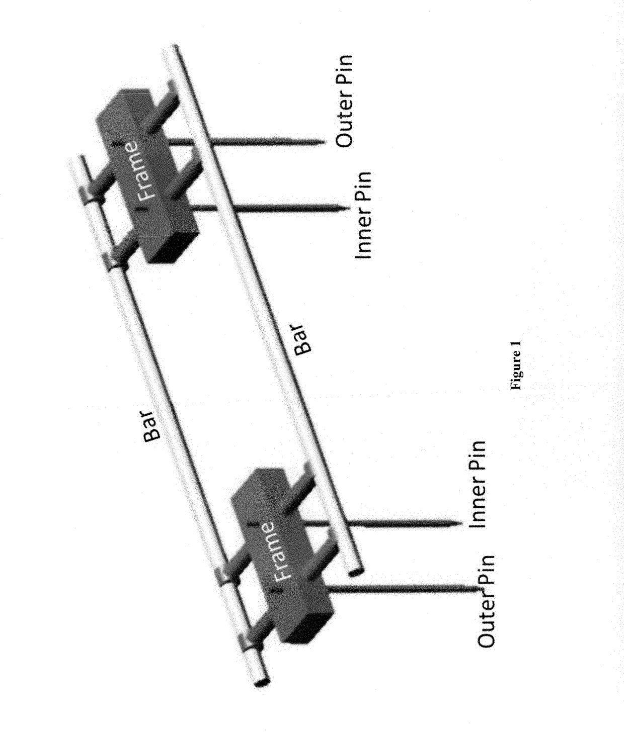
[0026]A typical external fixation device includes at least two connection bars, at least two stabilizing clamps between the two bars, at least one pin in each clamp that extends and penetrates into a human body to securely position the fixation device relative to the human body. Shown below in FIG. 1 is a top-side view of an example of the external fixation device that includes two connection bars (parallel as shown below), two clamps, and four pins (one inner pin and one outer pin in each of the two clamps), all of which are labeled and identified in FIG. 1. In this example, the lower part of the pins, including their tips, are immersed in a human body to secure the device's relative position to the human body.

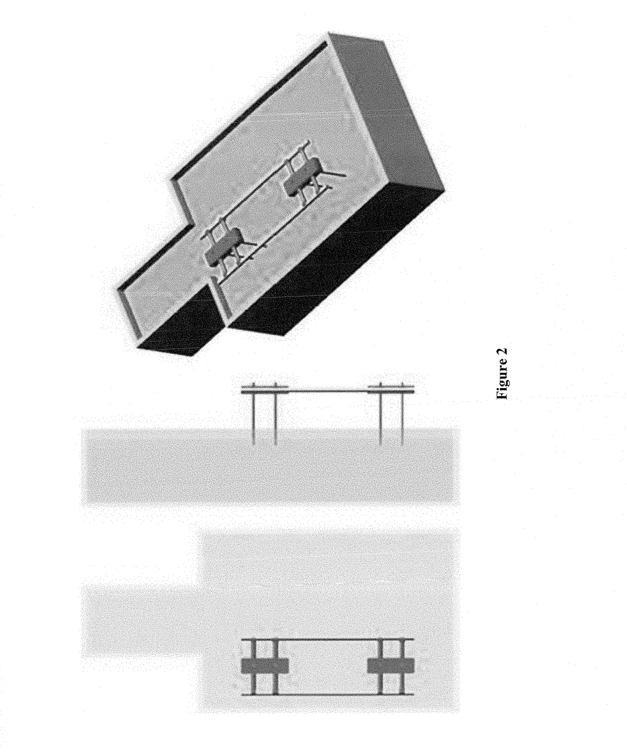
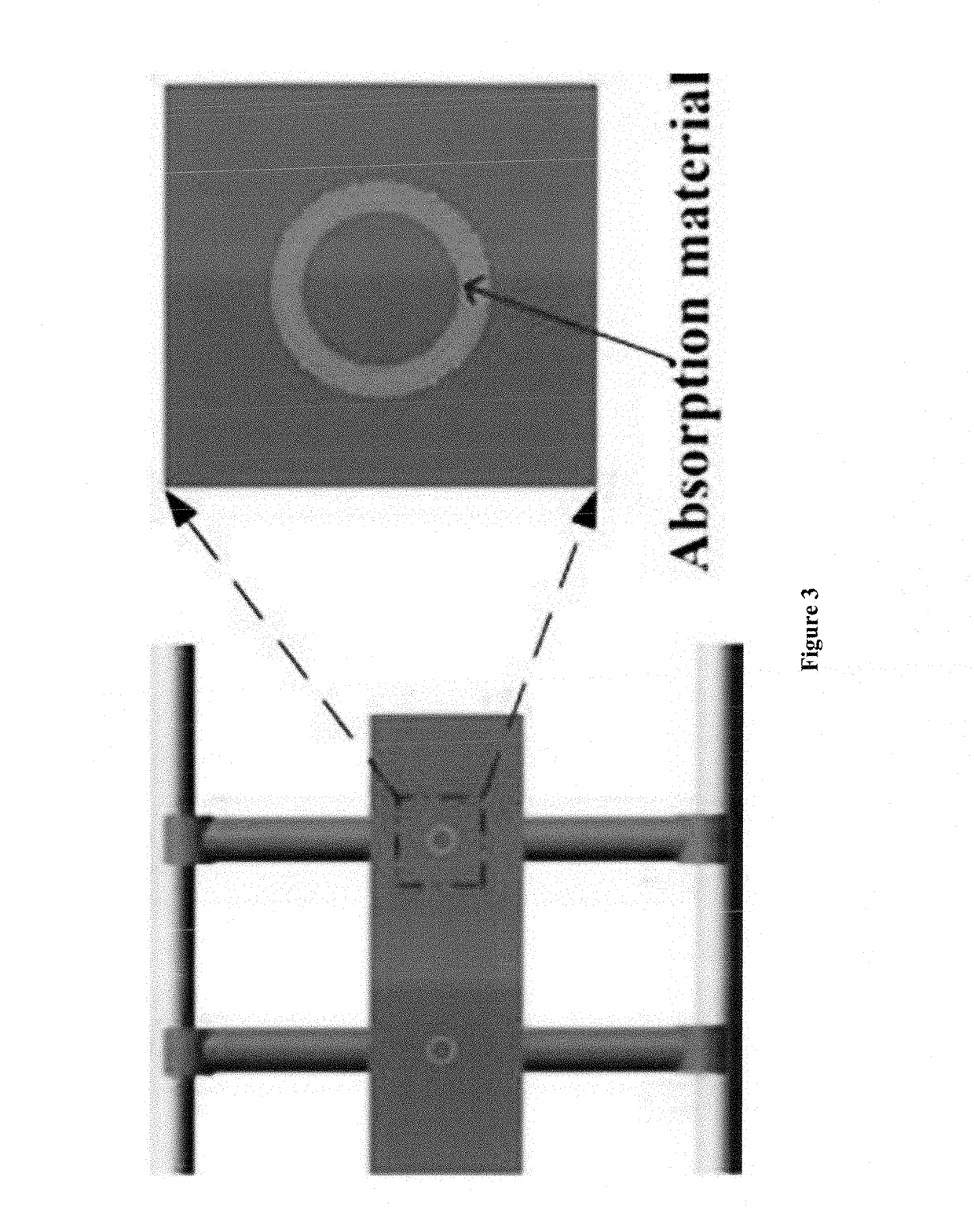
[0027]The present invention provides a novel and efficient solution to reduce RF induced heating in an external fixation device by utilization of an absorption material between different parts in the external fixation device. Not intended to be bound by the theory, it is beli...


PUM


Abstract

The present invention in general provides methods for reducing RF-induced heating in an external fixation device including at least two bars, at least two clamps and at least two pins; and external fixation devices with significantly lower RF heating at the pins' tips when compared to other external fixation devices.

Description

REFERENCE TO RELATED APPLICATIONS[0001]This application claims priority to U.S. application No. 62 / 113,271, filed on Feb. 6, 2015, and International Application No. PCT / US2015 / 053319, filed on Sep. 19, 2015, the contents of both of which are incorporated herein by reference in their entireties.BACKGROUND OF THE INVENTION[0002]Among all medical imaging techniques, there is an increasing trend to use magnetic resonance imaging (MRI) because of its non-ionized feature and high-resolution image quality. However, strong radio frequency (RF) fields generated by MRI systems can cause heating effects when patients are being scanned. This can be a significant issue when patients with metallic medical devices (e.g., external fixation devices) are scanned. Localized energy can be deposited near the tips of these medical devices, which may potentially lead to permanent tissue damage. This is particularly severe when patients with an external fixation device are being scanned for the fact that m...

Claims


Application Information

Patent Timeline
Patent Type & Authority Patents(United States)
IPC IPC(8): A61B17/60A61B5/055A61B17/64A61B17/62
CPCA61B17/60A61B5/0555A61B17/6466A61B17/62A61B5/055
Inventor CHEN, JI
Owner UNIV HOUSTON SYST
Learn More