
Pan for baking bread

a technology for baking bread and pans, applied in baking, baking-tins, food science, etc., can solve the problems of mould base wear, difficult handling, and fast heat transmission, and achieve the effect of reducing the risk of mold damage, and reducing the service life of the mold

Active Publication Date: 2019-03-05
COATRESA S L U +1
View PDF20 Cites 0 Cited by
  • Summary
  • Abstract
  • Description
  • Claims
  • Application Information

AI Technical Summary

Benefits of technology

[0011]The fastening device has the advantage that it effectively and safely prevents raising the cover without the need to resort to the use of plates with a heavy weight. In particular, it has been observed that with this fastening device the weight of the cover can be reduced to approximately 4 kg, which positively results in a large energy saving (quicker baking with smaller energy consumption). Furthermore, the pan is light and easy to handle.
[0030]In the present invention, recess is understood as a portion of the plate acting as a cover configured to penetrate in the inner cavity of each one of said moulds. These recesses are further configured so that each defines an insert “e” of the plate in the upper edge of the walls of the moulds. This insert “e” enables an adjustment of the plate in the inner cavity of the moulds where the dough is housed.

Problems solved by technology

Nevertheless, it has been observed that, in practice, despite the use of the cover, the existing pans obtain a loaf which has many irregularities or bulges on its surface.
However, during baking the bread dough may displace the plate that serves as a cover.
However, these plates hinder fast heat transmission and are difficult to handle.
Nevertheless, if the plate that configures the moulds is of little thickness the mould base will tend to easily wear during its displacement on the industry's transport chains.
On the other hand, if the plate acting as a cover is of little thickness, this plate moves during the baking of the bread preventing a loaf of uniform section from being obtained.
However, these reinforcing structures also hinder the uniform transmission of heat in certain areas, which translates into a less homogeneous baking which negatively affects obtaining a regular shaped loaf.

Method used


Image

  • Pan for baking bread
  • Pan for baking bread
  • Pan for baking bread

Examples


first embodiment

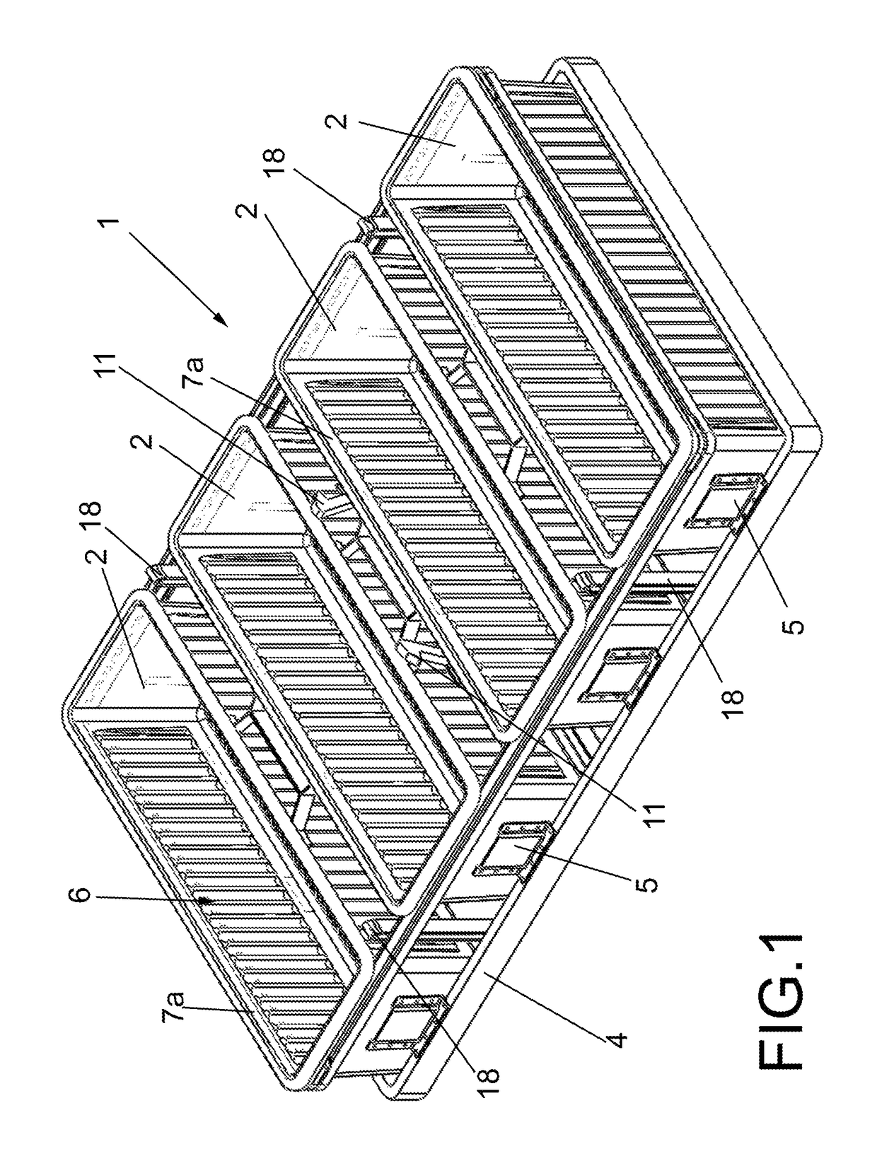
[0034]FIG. 1 is a perspective view of the pan provided with four baking moulds.

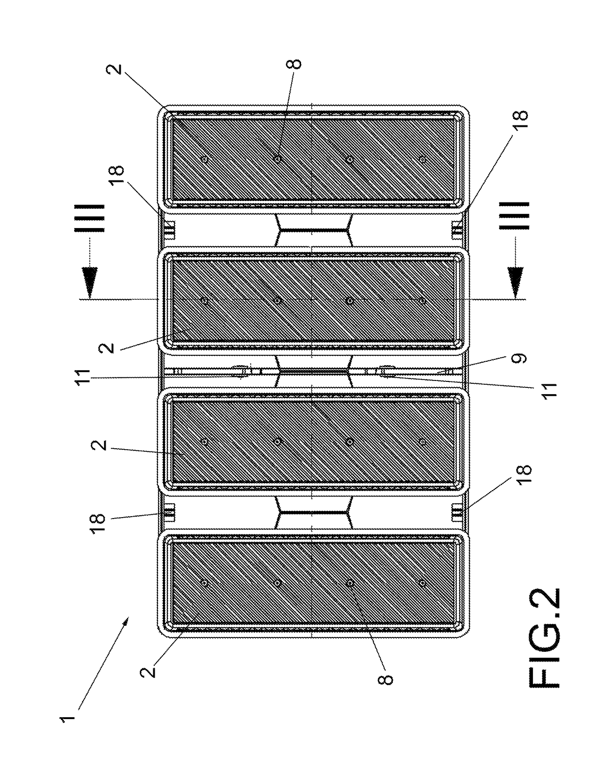
[0035]FIG. 2 is a plan view of the pan of FIG. 1.

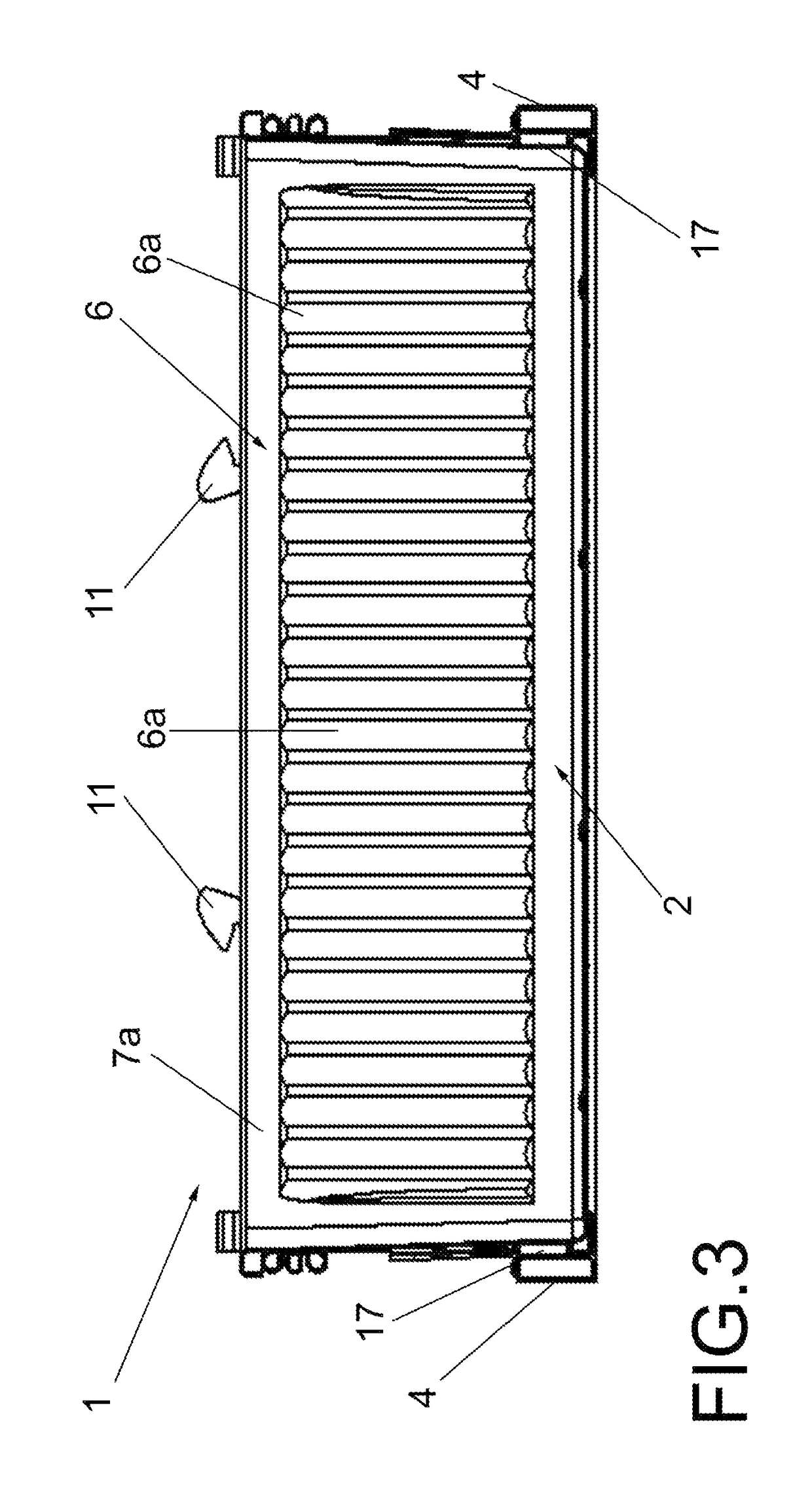
[0036]FIG. 3 is a section of the pan of FIG. 2.

[0037]FIG. 4 is a perspective view of the same pan of FIG. 1 provided with a cover.

[0038]FIG. 5 is a cross-section of the pan of FIG. 4 showing the fastening device of the cover.

[0039]FIG. 6 is a longitudinal section of the pan of FIG. 4.

[0040]FIG. 7 shows a detail of the section of FIG. 6.

[0041]FIG. 8 is a longitudinal section of the cover of the pan which shows the recesses.

[0042]FIG. 9 is a detail of the cover of FIG. 8 which shows a recess and the insert “e” defined by said recess.

second embodiment

[0043]FIG. 10 shows a perspective view of the pan. In this embodiment the hooks of the fastening device of the plate are joined to structures of the pan which hang joined to the walls of two moulds.

[0044]FIG. 11 shows a top perspective view of a plate which acts as a cover of the pan of the embodiment of FIG. 10.

[0045]FIGS. 12 and 13 are two cross-sections of the pan of FIG. 10 covered with the cover of FIG. 11. These sections diagrammatically show two ways of actuating the hook and the weight of the fastening device to release the plate acting as a cover.


PUM


Abstract

It comprises a plurality of baking moulds (2), a plate (3) acting as a cover of said pan (1), and means to prevent the raising of said plate as the bread is baked inside said moulds, and is characterized in that said means to prevent the raising of said plate comprise a fastening device (12) associated to a structure (9, 22) of said pan (1), said fastening device (12) including at least one hook (11) which is hingedly joined to a shaft (23) of said structure (9, 22), said hook (11) being susceptible of catching a portion (3a, 3b) of said plate (3) when it tilts on said shaft (23).

Description

[0001]The present invention relates to a pan for baking bread on an industrial scale which has a plate acting as a cover and is, nevertheless, light and easy to handle.BACKGROUND OF THE INVENTION[0002]Pans are known for baking the type of bread known as pan loaf on an industrial scale. These pans comprise a plurality of baking moulds and, in many cases, a plate acting as a cover of the pan.[0003]Said plate acting as a cover is placed to avoid the upper part of the bread from becoming convex and thus obtaining, insofar as possible, a loaf of uniform square or rectangular section which is easy to handle. Nevertheless, it has been observed that, in practice, despite the use of the cover, the existing pans obtain a loaf which has many irregularities or bulges on its surface.[0004]During the baking process of the pan loaf on an industrial scale, said pans are displaced empty along chains until reaching the production chain where the raw bread dough falls inside the moulds. Next, the pans...

Claims


Application Information

Patent Timeline
Patent Type & Authority Patents(United States)
IPC IPC(8): A21B3/13
CPCA21B3/134A21B3/135
Inventor MARIN MORO, TOMAS
Owner COATRESA S L U
Learn More