
Linear explosive disruptor

a technology of explosive disruptor and linear explosive, applied in the field of explosives, can solve the problems of lack of precision disruption capability, high velocities and kinetic energy, and devices posing a threat to personnel and property, and achieve the effects of reducing the recoil effect, dampening the impulse force, and maintaining the car's statur

Active Publication Date: 2019-02-26
BENSON MARK
View PDF85 Cites 8 Cited by
  • Summary
  • Abstract
  • Description
  • Claims
  • Application Information

AI Technical Summary

Benefits of technology

The present invention is a linear explosive disruption tool that can safely disable hazardous devices. The tool is lightweight, compact, and easy to use, and can be fired from both underwater and terrestrial robots without damaging them. The invention has several technical effects, including the use of a protective chamber to prevent collateral damage, limited recoil to reduce damage to the robot, foam materials to absorb energy and disperse explosive gases, and the ability to be used on underwater or terrestrial robots.

Problems solved by technology

These devices pose a threat to personnel and property due to the destructive potential of the explosive materials and compounds located within them.
These velocities can range anywhere from 1500 feet / sec to 6000 ft / sec, depending on the explosive disruption tool chosen, and often lack precision disruption capabilities.
While explosive tools have high velocities and kinetic energies, they cause considerable amounts of collateral damage when fired.
The detonation that takes place to excel the projectile or water makes the tool unbeneficial for situations where collateral damage must be minimized.
While these tools are effective, the projectile velocities are typically low in comparison to explosive disruption charges (less than 2,000 feet / sec).
In addition, the length, size, weight, and inability to reduce the recoil effects of these disruption tools makes them non-ideal for robot operations.

Method used


Image

  • Linear explosive disruptor
  • Linear explosive disruptor
  • Linear explosive disruptor

Examples


Embodiment Construction

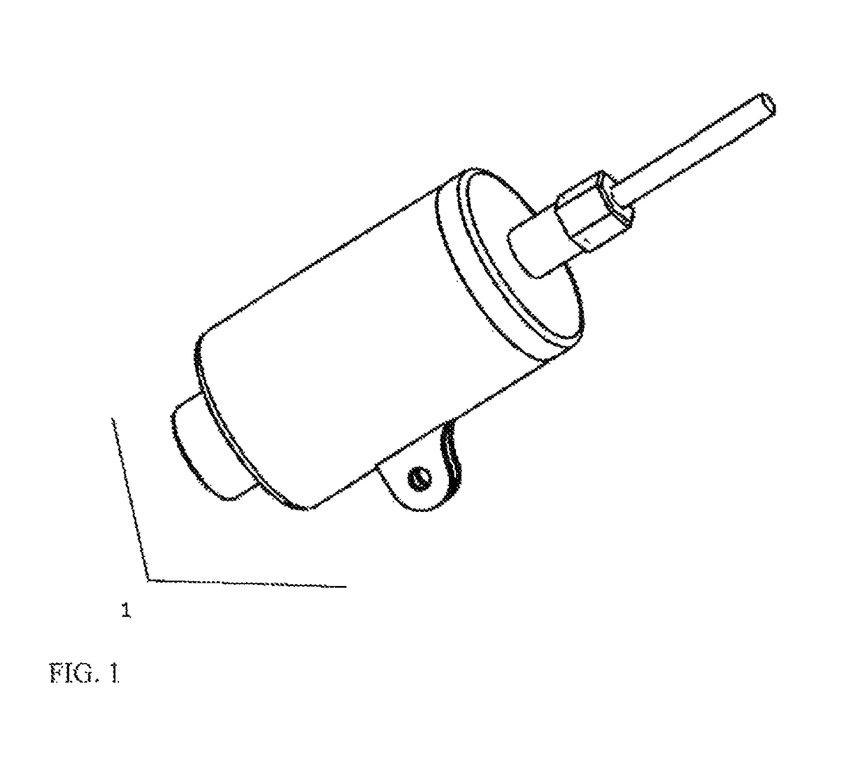
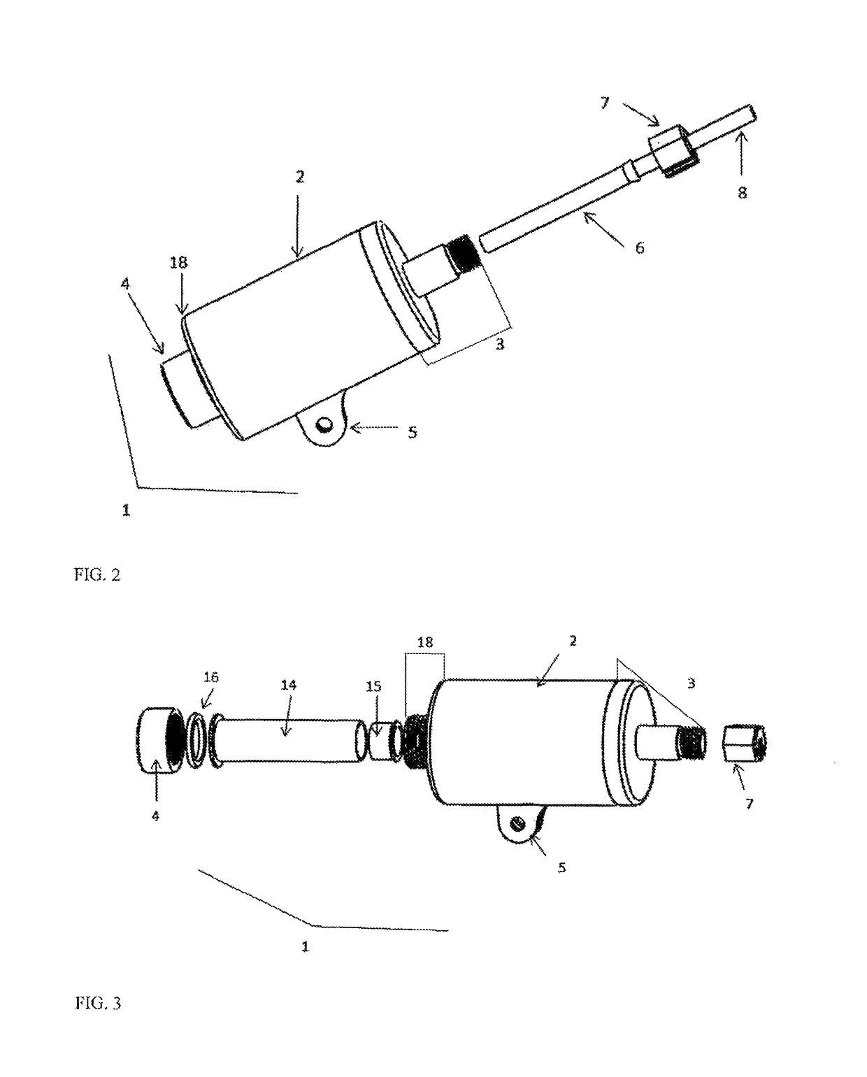
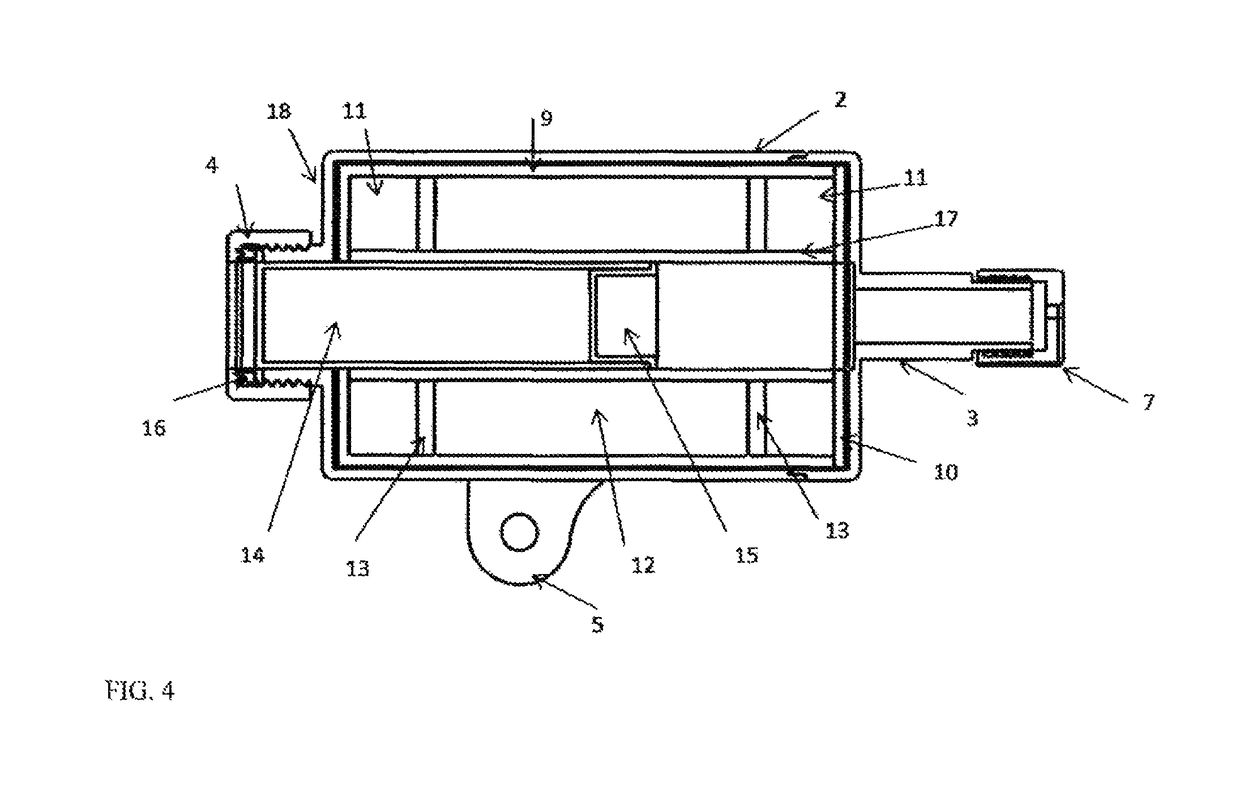
[0020]The present invention will now be described in detail with reference to the accompanying drawings, wherein the same reference numerals will be used to identify the same or similar elements throughout the several views. It should be noted that the drawings should be viewed in the direction of orientation of the reference numerals.

[0021]FIG. 1 illustrates a linear explosive disruption tool 1 that is configured for use against an underwater or terrestrial hazardous explosive device. The linear explosive disruption tool 1 may be integrated onto a robotic platform or may also be fired from a stand or other attachment device. An alignment or method of aiming the device is not included, but one of skill in the art may easily see that a number of standard methodologies may be employed to do so, such as a laser boresight, a mechanical alignment sight, or any type of fixed sight common to other firearms.

[0022]FIG. 2 is an illustration of the linear explosive disruption tool 1 with the b...


PUM


Abstract

A lightweight linear explosive disruption tool that may be used to fire a high speed projectile at a hazardous device in order to separate the components of the explosive train, thereby rendering it safe. The linear explosive disruption tool utilizes open cellular foam materials to prevent collateral damage of explosive gases and fragmentation that would otherwise prevent the device from being fired from a robot. An internal clapper tube distributes forces to the ligaments of cellular foam material and an external support tube contains the explosive fragmentation and blast overpressure. An internal barrel provides projectile travel in a single precision oriented direction and also reduces recoil which also enables the device to be fired from a robot as well. Such a tool prevents explosive gases and fragmentation from causing unnecessary collateral damage to the surroundings or supporting robot with reduced recoil effects.

Description

CROSS-REFERENCE TO RELATED APPLICATIONS[0001]This Nonprovisional application claims priority under 35 U.S.C. § 119(e) on U.S. Provisional Application No. 61 / 645,173 filed on May 10, 2012, the entire contents of which are hereby incorporated by reference in its entirety.TECHNICAL FIELD[0002]Embodiments of the present invention relate to the technical field of explosives. More particularly, the embodiments of the present invention are directed to disruption and rendering safe of explosive hazardous devices.BACKGROUND OF THE INVENTION[0003]Explosive hazardous devices include improvised explosive devices, unexploded ordnance, homemade explosives, or other explosive related items which are located either underwater or on land. These devices pose a threat to personnel and property due to the destructive potential of the explosive materials and compounds located within them.[0004]Personnel who are responsible for disarming or rendering safe explosive hazardous devices utilize explosive dis...

Claims


Application Information

Patent Timeline
IPC IPC(8): F42B3/08
CPCF42B3/08F42B3/006
Inventor BENSON, MARK
Owner BENSON MARK
Learn More