
Tool for a dismantlable medical instrument

a medical instrument and tool technology, applied in the field of tools for dismantling medical instruments, to achieve the effect of deep engagement and good form-fit engagemen

Active Publication Date: 2019-02-19
KARL STORZ GMBH & CO KG
View PDF7 Cites 0 Cited by
  • Summary
  • Abstract
  • Description
  • Claims
  • Application Information

AI Technical Summary

Benefits of technology

[0015]The design of the tool such that a cavity for receiving a distal end of a shank is provided on a first component and a catch for forming a bayonet connection is provided on a second component, and such that these two components are then rigidly connected to each other, can permit substantial miniaturization of the tool. Particularly when the tool and the shank have diameters in the range of 2 mm or less, formation of a catch directly on the first component is possible by milling, erosion or in some other way but with very great effort. The design of the catch on a second component provides leeway for further miniaturization of the tool diameter to 1.6 mm or less.
[0018]By means of a bearing being formed on the first component, it is possible for the tool to be formed exclusively (with the exception of one or more movable branches and mechanisms for their movement) of the first component and of the second component. This simple structure favors miniaturization and reduces the manufacturing costs.
[0025]The design of the second component with an annular area on which one or more catches are provided can simplify the manufacture and the handling of the second component. In particular, the annular area can be easily aligned with the proximal edge of the first component and optionally then joined to the latter.
[0034]The described structure of the transmission mechanism composed of only two components, namely the rod or tube and the endpiece, which nonetheless at the same time form the locking projection, permits a relatively simple structure and cost-effective manufacture.
[0041]The slit or the groove in the support tube can be arranged to be partially or completely congruent with the L-shaped slit or the L-shaped groove at the distal end of the shank tube. In particular, the slit or the groove in the support tube is straight and parallel and is partially or completely congruent with the abovementioned first portion or first limb of the L-shaped slit or of the L-shaped groove at the distal end of the shank tube. A congruent arrangement of mutually corresponding slits in the support tube and in the shank tube can permit particularly deep engagement of the locking projection and / or of the catch and, therefore, particularly good form-fit engagement.

Problems solved by technology

The technical manufacturing problem arising here is solved in particular by the fact that the catches are not manufactured together with a component that forms a cavity for receiving the distal end of a shank.

Method used


Image

  • Tool for a dismantlable medical instrument
  • Tool for a dismantlable medical instrument
  • Tool for a dismantlable medical instrument

Examples


Embodiment Construction

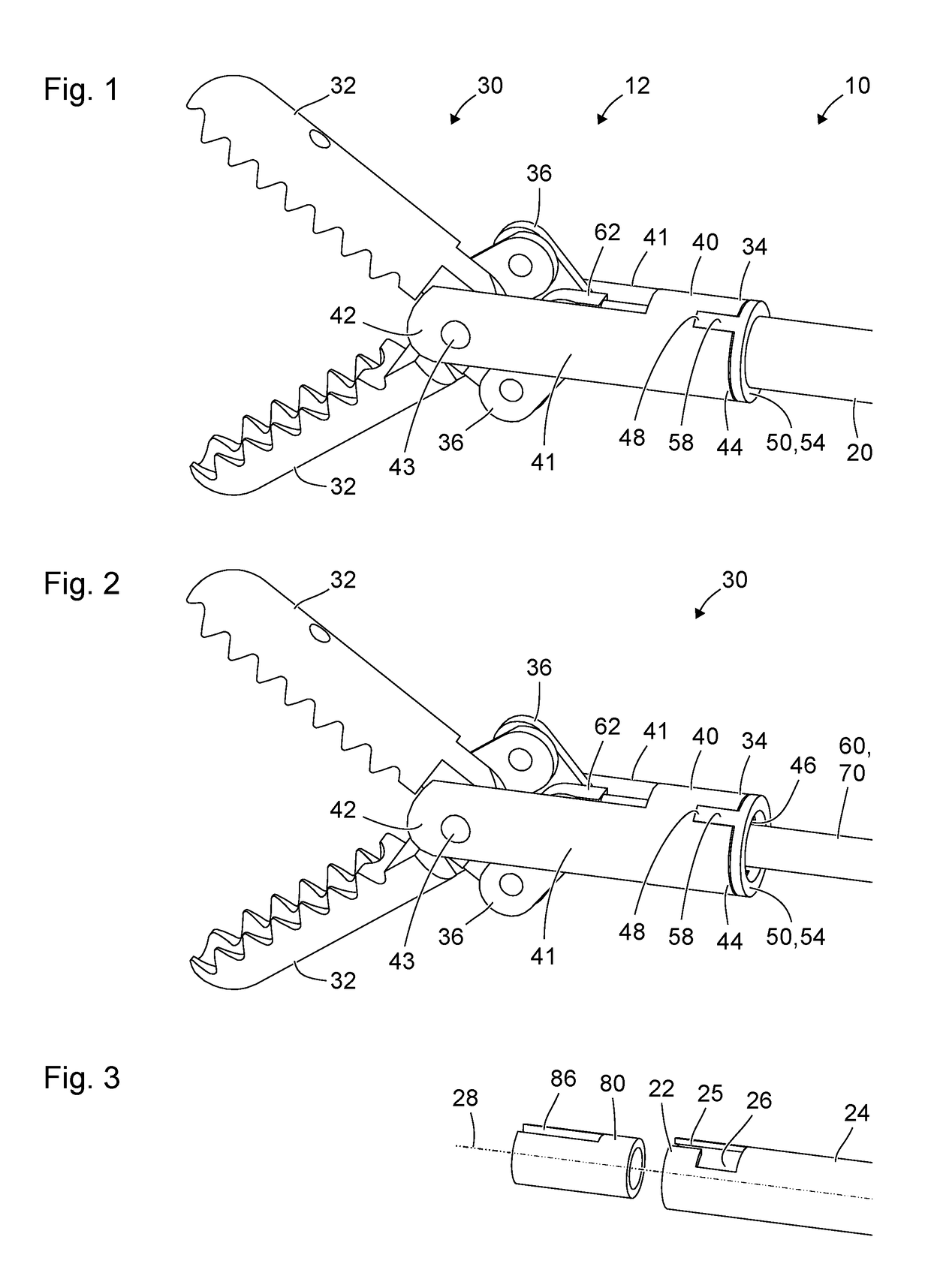
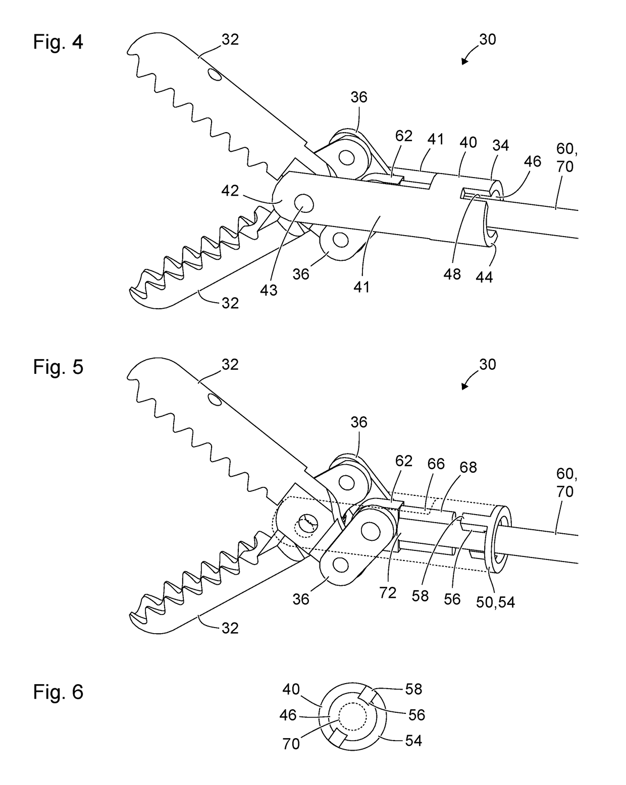
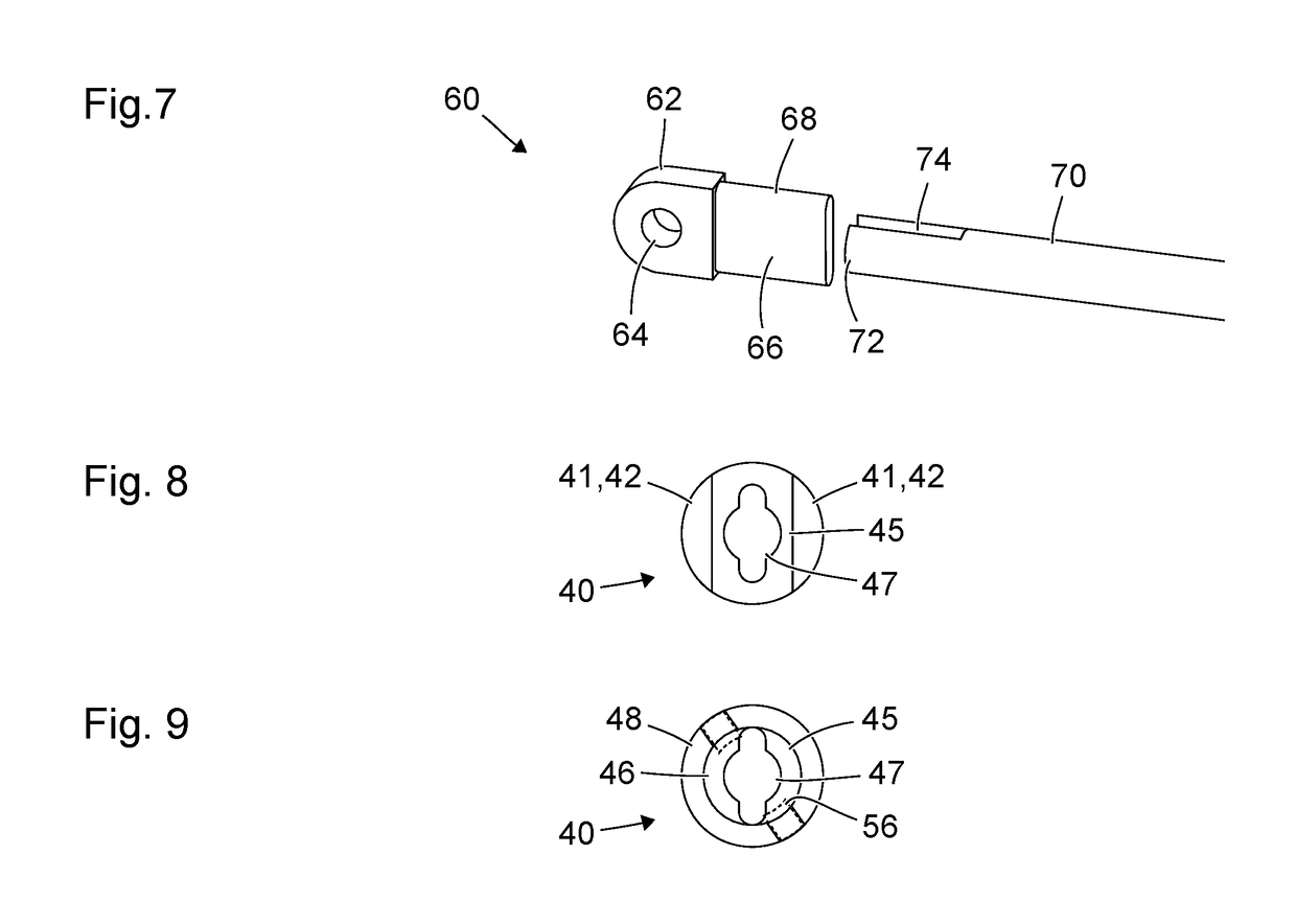
[0054]FIG. 1 shows a schematic axonometric view of a distal end 12 of a medical instrument 10 for micro-invasive applications in human or veterinary medicine. The medical instrument 10 has a long, thin, rigid or flexible (i.e. elastically deformable, or plastically deformable without destruction), straight or curved shank 20. The distal of the shank 20 is mechanically connected to a tool 30, in particular to the proximal end 34 thereof, in such a way as to be releasable without destruction. A manipulation mechanism for manually manipulating the medical instrument 10 can be provided at the proximal end of the shank 20.

[0055]The tool 30 comprises two branches 32 which are pivotable in opposite directions about the same pivot axis and which serve for the gripping, pinching, electrosurgical coagulation or cutting of tissue. The tool 30 comprises a first component or fork component 40 and a second component or catch component 50. The fork component 40 comprises two parallel side rails 41...


PUM


Abstract

A tool for a dismantlable medical instrument includes a first component, which surrounds a cavity for receiving a distal end of a shank, and a second component with a catch, which protrudes into the cavity surrounded by the first component to form a bayonet connection with a distal end of a shank protruding into the cavity, by engagement of the catch in a slit or a groove at the distal end of the shank. The first component has a recess into which the second component is fitted.

Description

[0001]This nonprovisional application claims priority under 35 U.S.C. § 119(a) to German Patent Application No. 10 2015 108 219.5, which was filed in Germany on May 26, 2015, and which is herein incorporated by reference.BACKGROUND OF THE INVENTION[0002]Field of the Invention[0003]The present invention relates to a tool for a dismantlable medical instrument, and to a dismantlable medical instrument.[0004]Description of the Background Art[0005]Laparoscopic and other micro-invasive medical procedures should be able to be performed through the smallest possible natural or artificial body openings and within the smallest possible cavities. Extremely thin medical instruments are required for this purpose. Moreover, for cleaning and sterilizing the tool after use and before a subsequent use, it is necessary or at least desirable that the instruments are able to be dismantled to the greatest possible extent.[0006]As the process of miniaturization continues, known and established concepts f...

Claims


Application Information

Patent Timeline
Patent Type & Authority Patents(United States)
IPC IPC(8): A61B90/00A61B17/29A61B17/00
CPCA61B90/08A61B17/00234A61B17/29A61B2017/2931A61B2017/00477A61B2017/294A61B2017/00296
Inventor KAERCHER, DANIELSTEFAN, JOCHEN
Owner KARL STORZ GMBH & CO KG
Learn More