
Nuclear density gauge

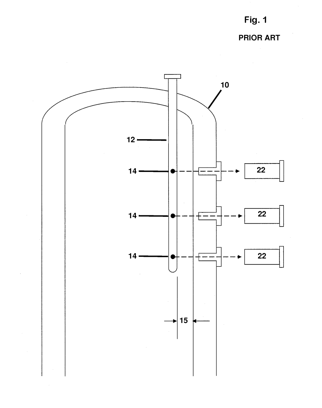
a technology of density gauge and nucleus, which is applied in the direction of optical radiation measurement, instruments, machines/engines, etc., can solve the problems of requiring some reconfiguration of sources and detectors, affecting the accuracy of calibration temperature, and expanding and contracting of vessels

Active Publication Date: 2019-02-05
VEGA AMERICAS
View PDF18 Cites 0 Cited by
  • Summary
  • Abstract
  • Description
  • Claims
  • Application Information

AI Technical Summary

Benefits of technology

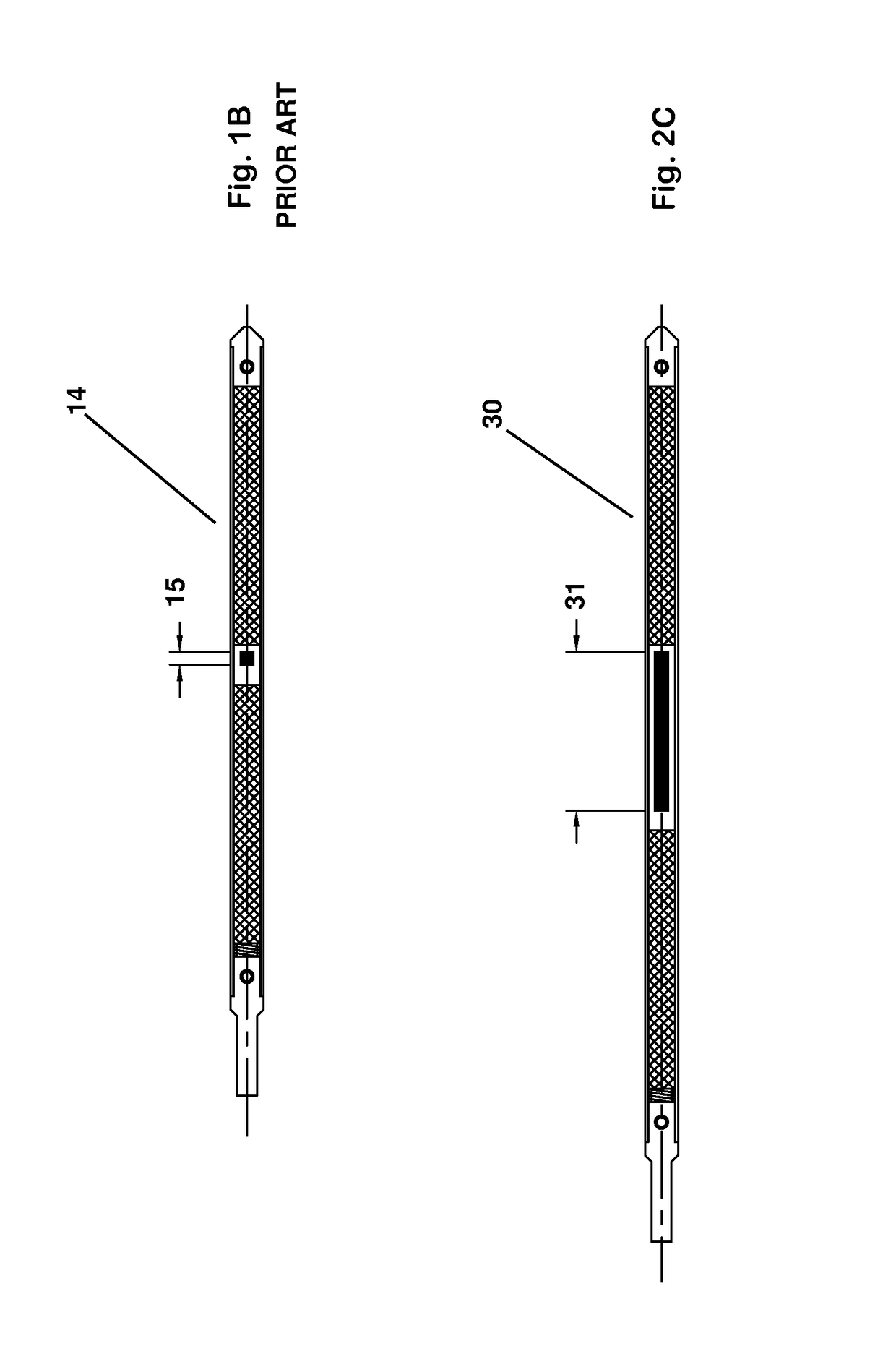
The present invention is about a level sensing gauge for a vessel that can detect the level of liquid or gas inside the vessel. The gauge comprises a source well and level sensing nozzles, which detect the radiation from the source well. The radiation pattern from the source nozzle is designed to illuminate a length of greater than one inch, so that changes in the vessel due to expansion or contraction will not significantly affect the detection. Additionally, the invention includes a level sensing radioactive source that provides a distributed activity pattern over a length greater than one inch to further improve the accuracy of the level sensing. The level sensing nozzles and wells are positioned next to each other, and the sources are configured to radiate energy towards the detectors. This arrangement ensures that the thermal expansion or contraction of the vessel does not significantly affect the detection.

Problems solved by technology

However, expansion and contraction of the vessel 10 tends to misalign a source and detector from the precise alignment at the calibration temperature.
Although the single nozzle solution described in the above-referenced and incorporated patent filings addresses the thermal alignment problems elegantly, it does require some reconfiguring of the sources and detectors and may not be attractive for some existing installations which are already outfitted with a source well and detectors aligned therewith.

Method used


Image

  • Nuclear density gauge
  • Nuclear density gauge
  • Nuclear density gauge

Examples


Embodiment Construction

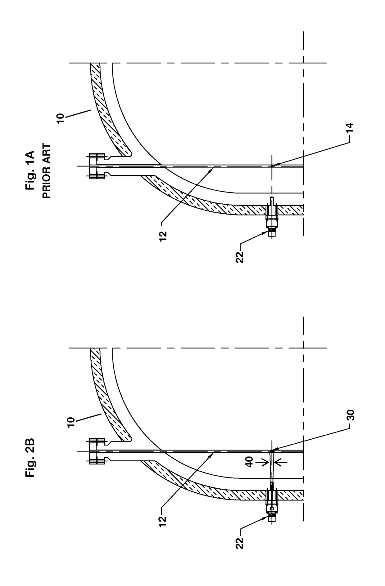
[0016]FIG. 2A illustrates a level sensing gauge configuration for a vessel 10 in accordance with the first aspect of the present, in which the point sources 14 shown in the embodiment of FIG. 1, are replaced with uniformly distributed sources 30, having a length dimension of 3 to 4 inches long. In this particular embodiment each point source, as in the prior art, is associated with a detector 22, positioned in a nozzle that extend through the vessel wall. In the particular illustrated embodiment, the nozzle extends through external insulation 32 surrounding the vessel, and terminates within the vessel wall 34 approximately 2.6 inches from the interior surface, as noted at 36.

[0017]The elongated dimension of the source 30 according to the principles of the present invention can be seen by reference to FIG. 2C. The desired length of the distributed activity is determined for each particular application, based upon the expected range of thermal expansion and contraction for the process...


PUM


Abstract

A nuclear level sensing gauge for a vessel 10 comprises a vertical source well 12 and one more level sensing detectors 22 mounted to vertically spaced nozzles, where the sources 30 in the source well 12 are distributed sources which emit a radiation pattern illuminating a length of greater than one inch of the respective level sensing nozzle, so that thermal expansion or contraction of the vessel 10 does not significantly alter radiation illuminating each detector 22. In a second embodiment, a vessel 10 includes plural level sensing nozzles and plurality of level sensing wells 12′, each nozzle and level sensing well 12′ positioned adjacent to one another such that a source in the well illuminates a detector 22 on the nozzle. Because the respective level sensing wells 12′ and level sensing nozzles are closely adjacent to one another, thermal expansion or contraction of the vessel does not significantly alter the illumination of the detector 22.

Description

CROSS-REFERENCE TO RELATED APPLICATIONS[0001]This Application claims the benefit of U.S. Provisional Application No. 61 / 535,351 filed on Sep. 15, 2011, which is related to application Ser. No. 13 / 190,461 filed Jul. 25, 2011 and to application Ser. No. 12 / 242,177 filed on Sep. 30, 2008, the entirety of each of which is hereby incorporated by reference in this application as if fully set forth herein.BACKGROUND OF THE INVENTION[0002]Problems have been experienced with level sensing in thick walled containers such as the vessel 10 seen in FIG. 1. Notably, a main variable in such environments is growth and shrinkage of the vessel with temperature. In some installations, a source well 12 is suspended from the top end of the vessel, about twenty to thirty inches from the interior vessel wall as seen at 15. Point source(s) are placed in the source well at locations aligned with one or more detectors 22.[0003]The point sources encapsulate the radioactive material distributed over a length o...

Claims


Application Information

Patent Timeline
Patent Type & Authority Patents(United States)
IPC IPC(8): G01F23/28G01F23/288
CPCG01F23/2885
Inventor CAHILL, BONAVENTURE
Owner VEGA AMERICAS
Learn More