
Bi-directional cable guard

a cable guard and bi-directional technology, applied in the direction of pipe protection, drilling pipes, mechanical equipment, etc., can solve the problems of uncontrollable detachment of the base and clamp, damage to the cable guard and cables, and loose taper pins, etc., to achieve the effect of quick installation and removal

Active Publication Date: 2019-02-05
NEFF SCOTT E
View PDF16 Cites 5 Cited by
  • Summary
  • Abstract
  • Description
  • Claims
  • Application Information

AI Technical Summary

Benefits of technology

The present invention provides a cable guard that overcomes shortcomings of previous cable guards by integrating a base and ring that are easy to manufacture, assemble, and install without the need for additional parts or tools. The base and ring are interchangeable and re-usable, and the structure is adaptable to different cable configurations. The base and ring are easily rotatably connected with ring rotational stops to prevent detachment and reduce the likelihood of personal injuries. The invention is also easy to assemble and may be installed with readily available equipment. The invention includes a combination of abutments, hinge abutment receivers, and hinge receivers that allow for easy assembly and prevent uncontrollable detachment. The invention is advantageous because it does not require complex assembly, may be shipped direct from a manufacturing facility, and assembled in the field to minimize storage, transportation, and labor costs.

Problems solved by technology

As downhole equipment and cable guards travels inside a casing, forces may damage cable guards and cables, loosen taper pins, and damage or crack corners, hinges, and blunt edges.
Taper pins require special equipment for assembly and mounting and taper pins may loosen during use.
Unfortunately, the hinge rod may be bent as it is bowed and / or pried with levers over a projection during assembly; or, after assembly, as the clamp and base are rotated to open the cable guard by over rotating the base where the outside of the base and clamp leverage against each other urging hinge portions out of the hinge grooves and further bending the hinge rod.
Consequently, when the base and clamp are rotated to close the cable guard, the bent hinge rod may pass around the projection and the base and clamp uncontrollably detach from each other.
However, like guard in the '027 patent, this guard also has sharp edges and elements that are subject to damage, cracking, and breakage.
Finally, this guard also includes pins, set screws, and bolts and fasteners with malleable elements that create opportunities for installation errors and failures or separation of the inserts and modular unit that may damage a well or equipment.
Separately manufactured hardened griping elements may detach, damage tubing, and require several manufacturing steps, complex tooling, and / or a separate core for manufacturing as a ductile iron casting.
First, apparatuses have multiple interconnecting and interengaging parts and some require at least one removable insert.
Third, cable guards require manufacturing and / or assembly of a set of parts of various materials or material properties or specially hardened elements.
Fourth, assembly, sliding, and over rotation may bend the hinge rod and / or u-bolt and cause the base and clamp and / or u-bolt to uncontrollably detach.
Fifth, inserts and separately hardened gripping elements require separate manufacturing steps and may become separated from cable guards and damage well equipment.
Seventh, inserts, taper pins, set screws, and bolts and fasteners with malleable elements make the cable guards complex and costly.
Eighth, taper pins require special power crimping equipment to assemble or mounting to tubing that increases assembly and installation complexity, and cable guards manufactured by stamping are less rigid and are subject to deformation and require costly shop space and press equipment.
Finally, the related art includes sharp edges and elements that are subject to damage, breakage, cracking, and failures and related cable damage.

Method used


Image

  • Bi-directional cable guard
  • Bi-directional cable guard
  • Bi-directional cable guard

Examples


first embodiment

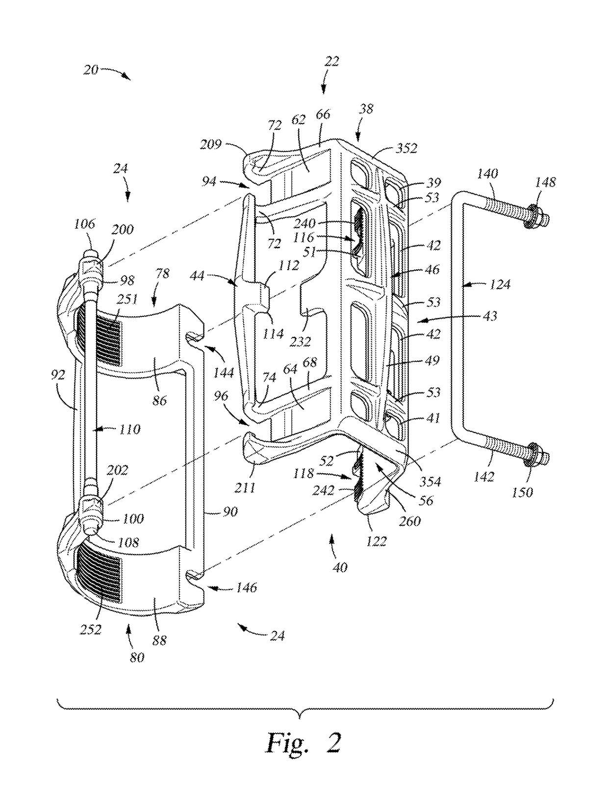
[0100]Referring to FIG. 1, a rig is engaged to a first tube 28 and a second tube 30, the tubes 28 and 30, that are removably connected to each other by a coupling 26 comprising a tubing string 32, and while coupling 26 is shown in the figures with squared ends, in practice coupling 26 may be integral and smoothly transition to tubes 28 and 30. FIG. 1 also shows a first cable 34 and a second cable 36, the cables 34 and 36, and a cable guard 20 enclosing cables 34 and 36 installed along tubing string 32. Referring to FIG. 1, below the deck, a cable guard 20 is deployed in a well bore 33. Typically, a well system 10 comprises tubing string 32 and cables 34 and 36 along tubing string 32, including cable guards 20 secured to the tubing string 32 that protect cables 34 and 36 extending to downhole equipment.

second embodiment

[0101]In general, referring to FIG. 1, the present invention is comprised of a base 22 and a ring 24 that are rotabably and removably connected to each other and adapted for mounting on tubing string 32, and a u-bolt 124 having threaded legs with nuts, described below, that is rotabably and removably connected to base 22; and, alternatively, in a second embodiment, u-bolt 124′ is rotabably and removably to ring 24′, for securing cable guard 20′ to tubing string 32′. Referring to FIG. 1, cable guard 20 is installed around coupling 26. The present invention may also be mounted on a tube and / or connected in tandem for protecting cables.

[0102]While the terms tube 28 and tubes 28 and 30 and tubing string 32 are related to each other as a tubing string 32 is comprised of tubes 28 and 30 and couplings 26, all embodiments of the present invention are capable of protecting cables 34 and 36 by mounting present invention on a tube 28 or on tubes 28 and / or 30 across a coupling 26. Similarly, th...


PUM


Abstract

A cable guard (20) for enclosing and protecting at least one cable (34) extending alongside a tube (28) comprising, a base (22), a ring (24), and a u-bolt (124), the base (22) has hinge receivers (72 and 74) to receive hinge pins (106 and 108) for rotatably and removably connecting base (22) and ring (24), and the ring (24) includes u-bolt receivers (70 and 71) for rotatably and removably connecting u-bolt (124) and ring (22), the ring (22) includes ring rotational stops (200 and 202) to prevent over rotation and uncontrollable detachment of the base (22) and ring (24); the base (22) includes u-bolt slots (116 and 118) and the ring (24) includes u-bolt leg receivers (144 and 146) for cooperating with the u-bolt slots (116 and 118) and receiving the u-bolt legs (140 and 142) in the base (24), whereby the cable guard (20) is assembled, at least one cable (34) is enclosed, the cable guard (20) is mounted, and the u-bolt (124) is tensioned by tightening the nuts (148 and 150) and as tension increases along with respective reactive forces the cable guard (20) is frictionally engaged to tube (28).

Description

CROSS REFERENCE TO RELATED APPLICATIONS[0001]The following application contains subject matter related to the present invention: 1) application Ser. No. 08 / 642,575 filed on or about Mar. 30, 2006; which is incorporated by reference in its entirety.FEDERALLY SPONSORED RESEARCH[0002]Not Applicable.SEQUENCE LISTING OR PROGRAM[0003]Not Applicable.BACKGROUND OF THE INVENTION1. Field of the Invention[0004]This present invention relates generally to improvements in protective devices, and, more particularly, to improvements in cable guards for protecting cables along tubes and couplings in a tubing string.2. Description of the Related Art[0005]Cable guards have been known for many years. Generally, cable guards are manufactured as fabricated, cast, molded, and / or stamped apparatuses and include a set of parts for assembly and installation. Installation parts typically include bolts, nuts, taper pins or other fasteners for assembly and to secure the cable guard to a tubing string. Assembly ...

Claims


Application Information

Patent Timeline
IPC IPC(8): F16L3/10H02G3/04
CPCF16L3/1075H02G3/0418H02G3/0456H02G3/32F16L57/06F16L3/2235F16L3/23E21B17/1035
Inventor NEFF, SCOTT E.
Owner NEFF SCOTT E
Learn More