
Light device

a light device and light technology, applied in the direction of instruments, lighting and heating apparatus, fibre light guides, etc., can solve the problems of increasing the required packaging space, requiring additional molding parts, and requiring a relatively thick packaging space, so as to reduce the amount of packaging space needed, eliminate shortcomings and disadvantages

Active Publication Date: 2019-01-22
VARROC LIGHTING SYST SRO
View PDF9 Cites 1 Cited by
  • Summary
  • Abstract
  • Description
  • Claims
  • Application Information

AI Technical Summary

Benefits of technology

The present invention is a light device that solves the problems of previous designs. It achieves this by eliminating the need for a separate molded exterior lens and interior light guide, as well as a separate mold tool and molding operation. Additionally, it significantly reduces the amount of space needed for a light guide by combining the outer lens and the light guide into a single item. This results in a thicker overall device, but it offers the benefits of streamlined manufacturing and reduced packaging requirements.

Problems solved by technology

A disadvantage of this design is that it requires a relatively thick packaging space to accommodate the lens cover and several light sources to achieve a uniform appearance.
A disadvantage of this design is that it still requires a secondary lens to act as an outer lens to protect the light guide.
This increases the required packaging space and requires an additional molded part for the exterior lens.
Additionally, this design does not address a method for extracting light from the guides.
This requires significant packaging space for the lamp, which is not available in certain applications.
Many lamps, particularly; side repeaters, side mounter turn signals, and applique lamps; have very narrow packaging space requirements, which makes it difficult and in some cases not possible to fit a light guide and an outer lens with an air gap between.
This type of design is also undesirable for the applications mentioned because it requires too much package space because space is required for multiple lenses as well as clearance spaces to account for variations in assembly and molding.

Method used


Image

  • Light device
  • Light device
  • Light device

Examples


Embodiment Construction

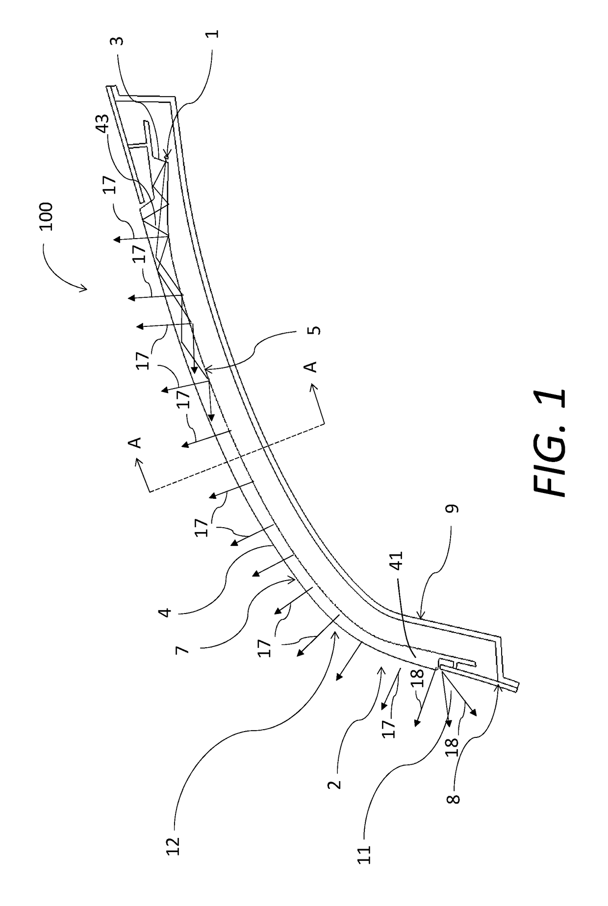
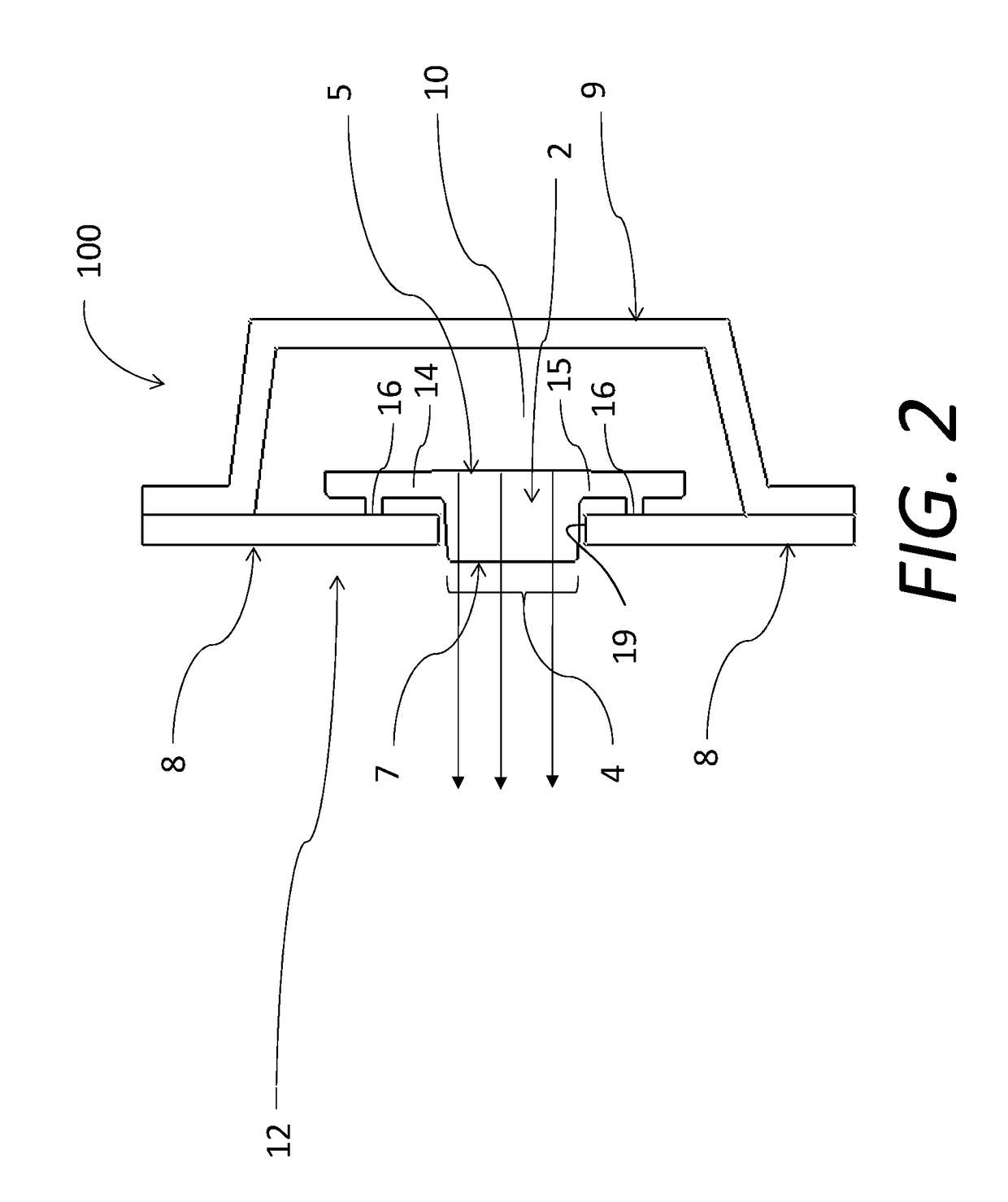
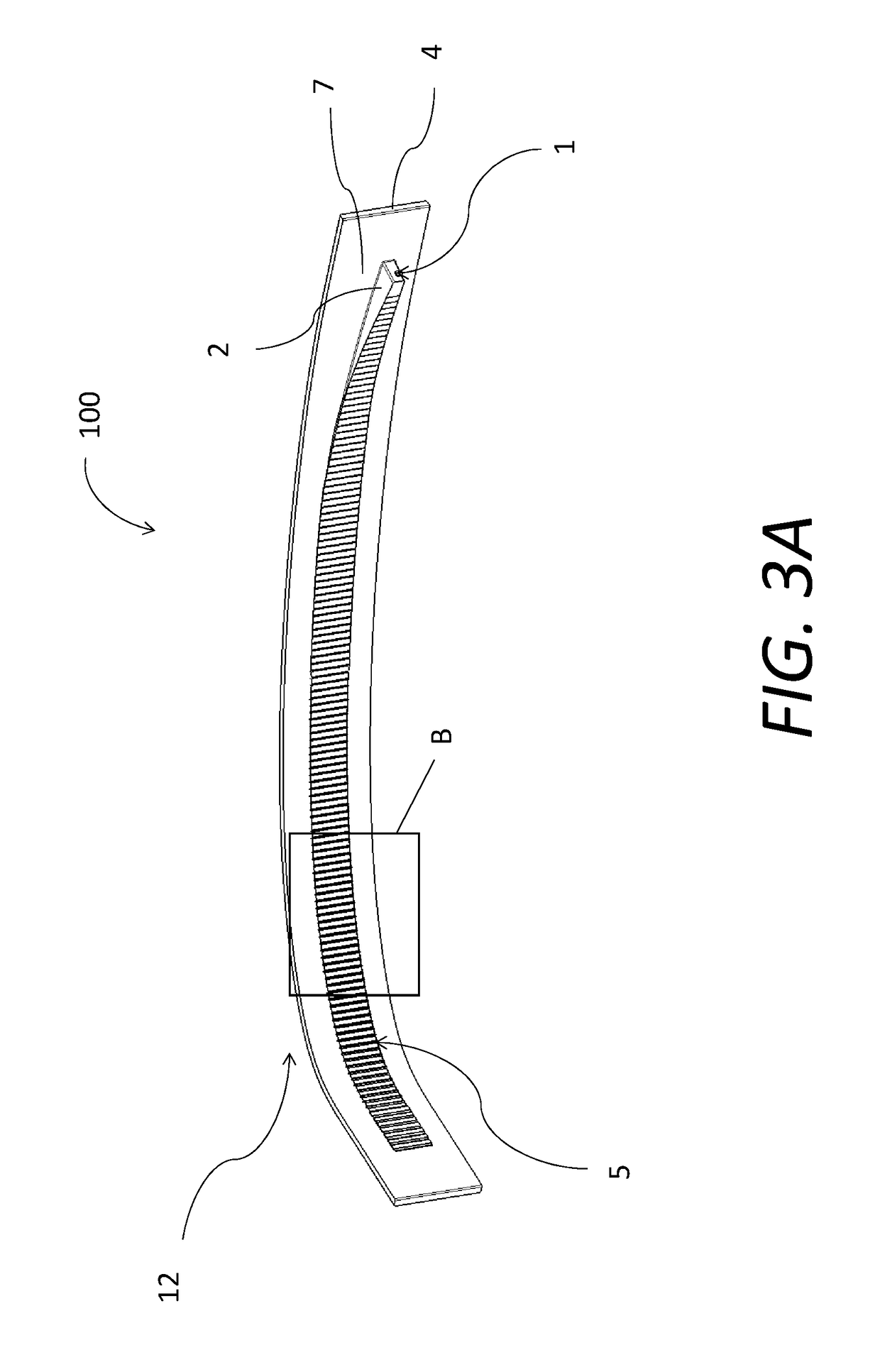
[0021]Referring now to the Figures, where the invention will be described with reference to specific embodiments, without limiting same, the light or lighting device 100 in accordance with the invention is explained with the use of drawings. The light device 100 may be employed in any suitable application or design, including as a light device 100 for various vehicles or in various vehicular applications, particularly in all manner of automotive vehicles. In one embodiment, the lighting device 100 comprises a vehicular exterior lighting device or a vehicular interior lighting device. In one embodiment, a vehicular exterior lighting device comprises a side mirror light, a tail light, a parking light, a running light, or a head light. FIG. 1 shows a longitudinal section view of the light guide 2 in which the exit face or surface 4 for emission of light rays 17 is combined with outer lens 7. The ends of the lens 7 / light guide 2 as well as the light source 1 and optical in-coupling area...


PUM


Abstract

A lighting device includes a housing, the housing comprising an opening. The lighting device also comprises a lens operably disposed in the opening, the lens having an outer viewable face and an opposed inner face, the lens comprising an integrally formed axially-extending light guide, the light guide comprising a light inlet end, a light outlet comprising a portion of the outer viewable face, and a light transmission portion, the light transmission portion comprising a light reflecting structure disposed on the inner face. The lighting device also includes a light source, the light guide configured to receive light rays from the light source into the light inlet end, transmit the rays via internal reflectance along light transmission portion to the light reflecting structures where they are reflected outwardly away from the lighting device in a principal direction through the outer viewable face.

Description

TECHNICAL FIELD[0001]The invention relates to a new light device for motor vehicles comprising an LED light source and an elongated light guide.BACKGROUND OF THE INVENTION[0002]In the field of lighting technology, light emitting diodes, referred to with the abbreviation LED, are frequently used as a light source instead of the conventional halogen bulbs. Among the lights of motor vehicles light guides occupy a special position as their elongated shape makes them especially suitable to create light lines positioned along the outline of headlights, or separately to create warning lights, e.g. positional, brake, indicator, or daily orientation lights. At present, light guides often fulfill signal light functions subject to higher requirements for the luminous flux, e.g. the day-time running lamps in headlights and the rear brake and direction indication lights in the rear lamps. Sometimes they are used where a bright, uniform appearance for the side repeater, which is incorporated into...

Claims


Application Information

Patent Timeline
Patent Type & Authority Patents(United States)
IPC IPC(8): F21V9/00F21S43/239F21S41/24F21S43/245F21V8/00F21S43/14F21S43/237F21S43/247
CPCF21S43/239F21S41/24F21S43/14F21S43/237F21S43/245G02B6/0038G02B6/0053G02B6/0065F21S43/247G02B6/003G02B6/001
Inventor CHILDRESS, COLBY J.PELECH, TIMOTHY
Owner VARROC LIGHTING SYST SRO
Learn More