
Monitoring a discharge in a plasma process

a plasma process and discharge technology, applied in the direction of electric discharge tubes, measuring devices, instruments, etc., can solve the problems of increasing the requirements of generators, unable to establish a fixed value, and generally too slow type of identification of arcs, so as to reduce the number of lines. , the effect of low transmission ra

Active Publication Date: 2019-01-15
HUETTINGER ELECTRONICS GMBH & CO KG
View PDF76 Cites 14 Cited by
  • Summary
  • Abstract
  • Description
  • Claims
  • Application Information

AI Technical Summary

Benefits of technology

The patent text describes devices, methods, and systems that can quickly and reliably identify arcs. This is achieved by measuring the time difference and signal amplitude difference between two signals and adding them to the first signal path. The technology can operate easily and quickly, providing a reliable and efficient way to detect arcs.

Problems solved by technology

A problem is that, for a periodically changing output signal of the power generator, it is not possible to establish a fixed value for a voltage breakdown or current increase because the current and voltage are intended to change continuously as a matter of principle.
Since such an establishment has to be carried out over a plurality of periods, this type of identification of an arc is generally substantially too slow and is often in the region of a few hundred milliseconds.
When the generators are used in the semiconductor production process, in particular flat panel display (FPD) production, however, increased requirements are placed on the generators.
This method may also result in erroneously identified arcs in the case of a very high number of reference values and very well-adjusted tolerances.

Method used


Image

  • Monitoring a discharge in a plasma process
  • Monitoring a discharge in a plasma process
  • Monitoring a discharge in a plasma process

Examples


first embodiment

[0120]FIG. 6 shows an output oscillating circuit 53a, as may be provided in FIG. 1 and FIG. 5 as an output oscillating circuit 53. The output oscillating circuit 53a may have a parallel oscillating circuit 60. The parallel oscillating circuit 60 may have a capacitor 61 and an inductor 62 which are both connected to the output of the bridge circuit in parallel. The inductor 62 may be part of a transformer.

[0121]An additional series capacitor 63 may be connected in series between the parallel oscillating circuit 60 and the plasma process.

second embodiment

[0122]FIG. 7 shows an output oscillating circuit 53b, as may be provided in FIG. 1 and FIG. 5 as an output oscillating circuit 53. The output oscillating circuit 53b may have a series oscillating circuit 64. The series oscillating circuit 64 may have a capacitor 66 and an inductor 65 which are connected in series between the output of the bridge circuit and the plasma process.

[0123]An additional parallel capacitor 67 may be connected in parallel between the two lines which connect the series oscillating circuit and the plasma process.

[0124]FIG. 8 shows an embodiment of an alternating current voltage production device 52a, as may be provided in FIG. 1 and FIG. 5 as an alternating current voltage production device 52. It has a bridge circuit 70 which is provided in this embodiment as a full bridge circuit with four switching elements 72, 73, 74, 75. The switching elements may preferably be transistors. IGBT or MOS-FET are particularly preferred. A uniform voltage is supplied to the br...


PUM


Abstract

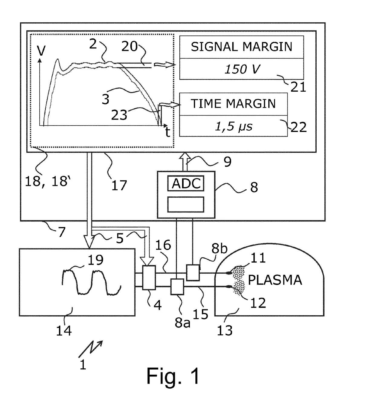
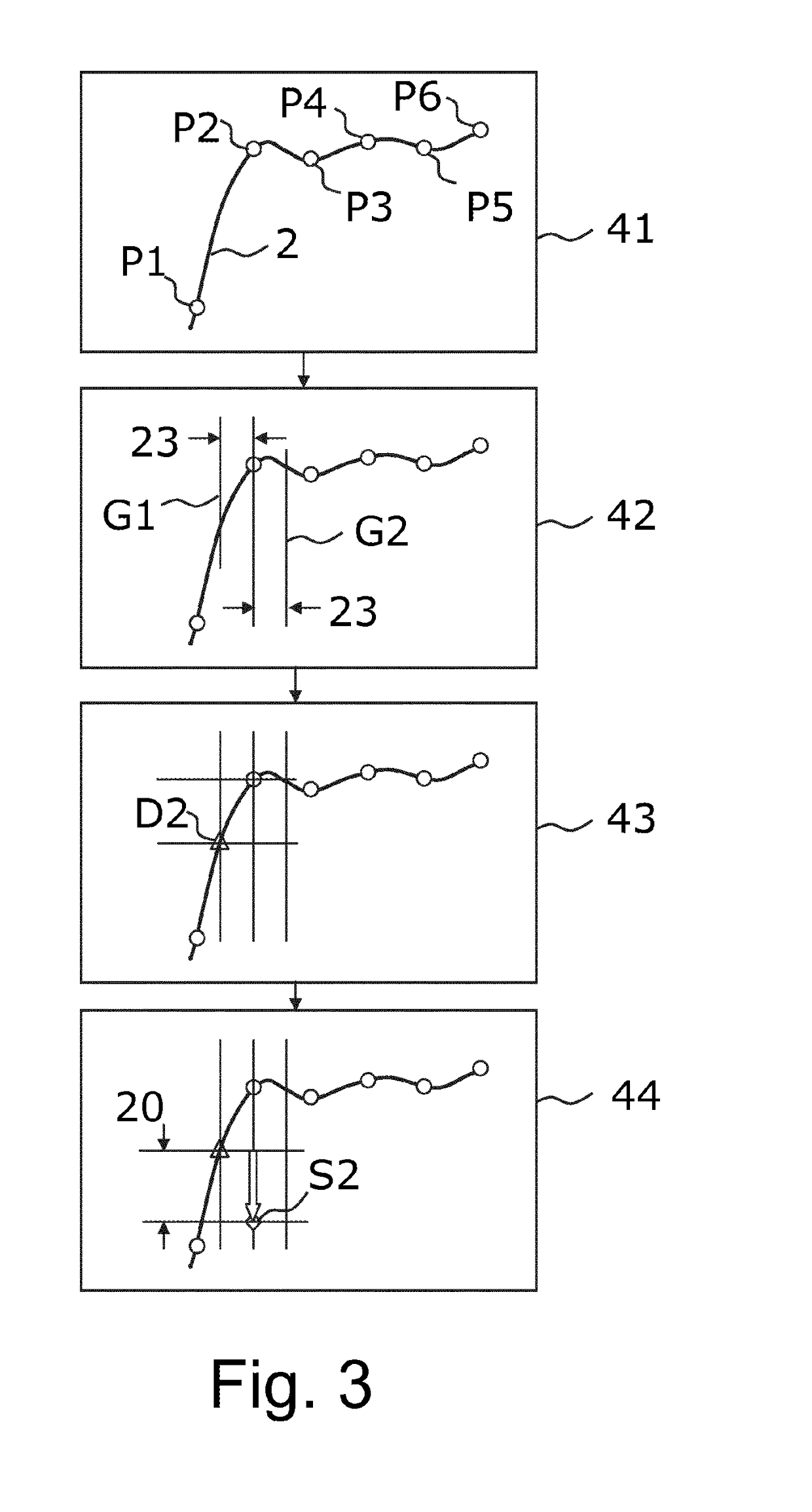
Devices and methods for monitoring a discharge in a plasma process are provided. An example method includes detecting at least a first signal path of at least one plasma supply signal within at least a first time range within at least one period of the plasma supply signal, detecting at least a second signal path of the at least one plasma supply signal within at least a second time range which is at the point corresponding to the first time range in at least one other period of the plasma supply signal, and generating an identification signal if the second signal path deviates by at least a distance from the first signal path. The distance has a minimum time difference and a minimum signal amplitude difference. The method enables to identify arcs in a very reliable and very rapid manner.

Description

CROSS-REFERENCE TO RELATED APPLICATIONS[0001]This application is a continuation of and claims priority under 35 U.S.C. § 120 to PCT Application No. PCT / EP2014 / 070856 filed on Sep. 30, 2014, which claims priority to German Application No. DE 10 2013 110 883.0, filed on Oct. 1, 2013. The contents of both of these priority applications are hereby incorporated by reference in their entireties.TECHNICAL FIELD[0002]The invention relates to monitoring a discharge in a plasma process, in particular between electrodes of a cathode sputtering arrangement, to which power is supplied by a power generator with a periodically changing output signal of the power generator.BACKGROUND[0003]The coating of substrates, for example, glass faces, by means of cathode sputtering in plasma processes, both in a reactive manner and in a conventional manner, is, for example, known from architectural glass coating. To that end, a plasma which carries material away from a target which is deposited on the substra...

Claims


Application Information

Patent Timeline
Patent Type & Authority Patents(United States)
IPC IPC(8): H01J37/32G01R31/12G01R19/00
CPCH01J37/32009G01R19/0061G01R31/12H01J37/32944H01J37/32926H01J37/32935H01J37/32917
Inventor LEYPOLD, DANIELRICHTER, ULRICHWUNN, FABIAN
Owner HUETTINGER ELECTRONICS GMBH & CO KG
Learn More