
Vehicle control device and vehicle control method

a technology of vehicle control and control device, which is applied in the direction of mechanical equipment, transportation and packaging, roads, etc., can solve the problems of deterioration of drivability, shock involved in clutch engagement, and drop in durability of starter motor, so as to suppress the effect of drivability

Active Publication Date: 2019-01-08
NISSAN MOTOR CO LTD
View PDF16 Cites 2 Cited by
  • Summary
  • Abstract
  • Description
  • Claims
  • Application Information

AI Technical Summary

Benefits of technology

This solution improves fuel efficiency by reducing starter motor wear and minimizes drivability shocks during clutch engagement, ensuring reliable engine starting and maintaining vehicle performance.

Problems solved by technology

The engine is generally started by using a starter motor, but since the number of engine start times drastically increases in a vehicle with the inertia traveling mode onboard, there is a concern of a drop of durability of the starter motor.
Thus, instead of the starter motor, push-start by engaging a clutch of the transmission which has been disengaged and by starting the engine by kinetic energy can be considered, but with this method, a shock is involved when the clutch is engaged, and drivability is deteriorated.

Method used


Image

  • Vehicle control device and vehicle control method
  • Vehicle control device and vehicle control method

Examples


Embodiment Construction

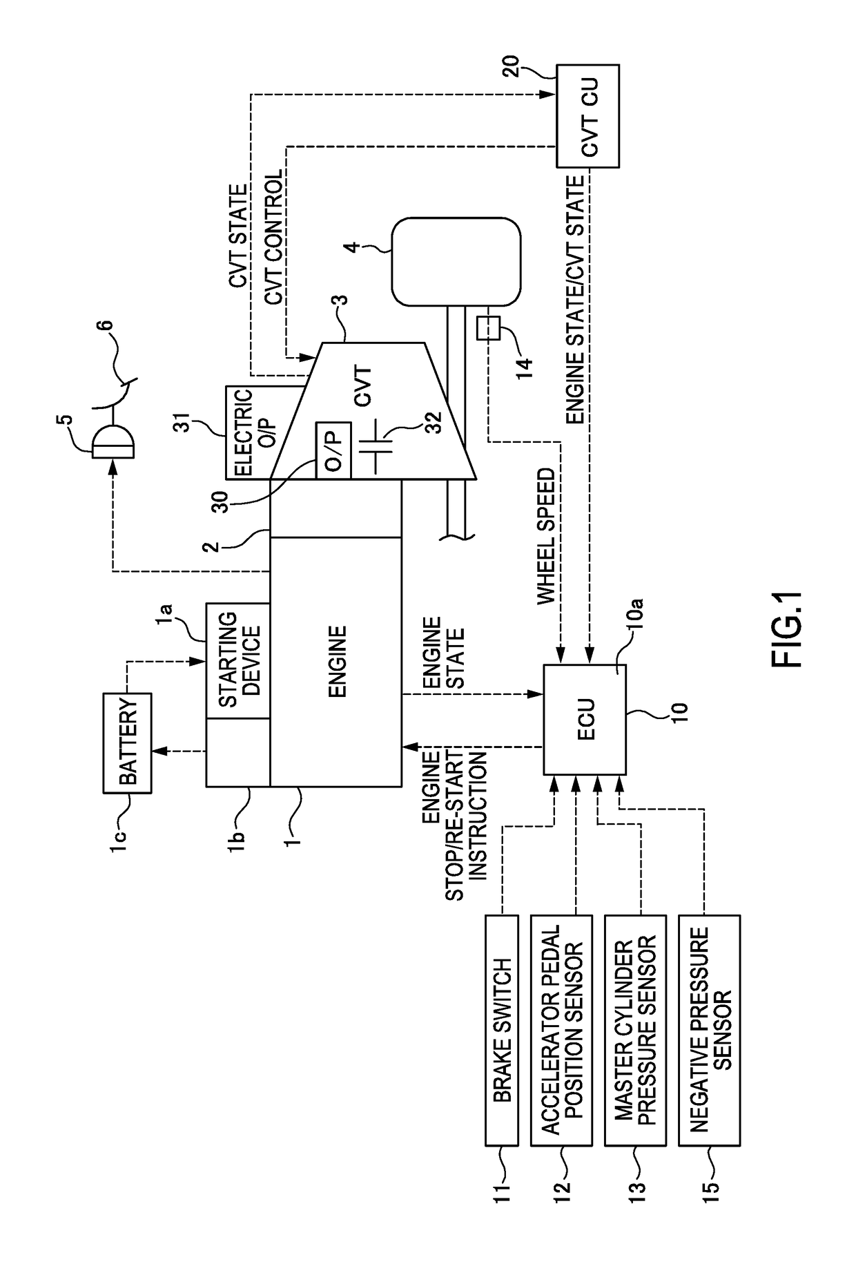
[0010]Embodiments of the present invention will be described below with reference to the attached drawings. In embodiments of the invention, numerous specific details are set forth in order to provide a more thorough understanding of the invention. However, it will be apparent to one of ordinary skill in the art that the invention may be practiced without these specific details. In other instances, well-known features have not been described in detail to avoid obscuring the invention. FIG. 1 is a schematic diagram of a vehicle including a vehicle control device according to one or more embodiments of the present invention. A torque converter 2 is provided on an output side of an engine 1 which is an internal combustion engine. A belt-type continuously variable transmission 3 is connected to an output side of the torque converter 2. A revolution driving force output from the engine 1 is input into the belt-type continuously variable transmission 3 through the torque converter 2 and s...


PUM


Abstract

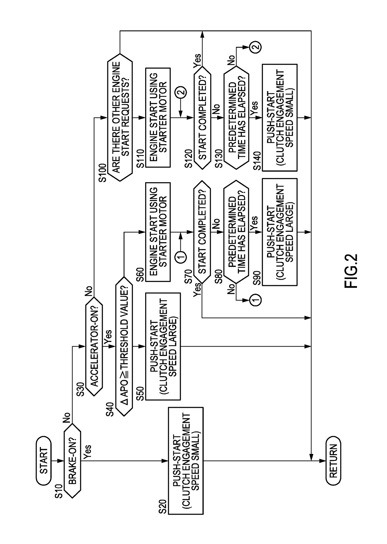
A vehicle control device disengages a clutch provided between an engine and a driving wheel at a brake-off and an accelerator-off during traveling of the vehicle, and stops the engine and carries out inertia traveling. The vehicle control device starts the engine by the push-start by engaging the clutch and by transmitting the power of the driving wheel to the engine, if it is determined that a brake pedal has been depressed during the inertia traveling.

Description

BACKGROUND[0001]Technical Field[0002]The present invention relates to a vehicle control device and a vehicle control method.[0003]Related Art[0004]JP2013-204624A discloses a technology that, if a state of accelerator-off and brake-off is brought about during traveling of a vehicle, a transmission is brought into a neutral state, and the vehicle is made to run with inertia.SUMMARY OF INVENTION[0005]In order to maximize improvement in fuel efficiency during inertia traveling, it may be desirable that an engine be stopped. If the engine is stopped during an inertia traveling mode in which inertia traveling is carried out, the engine needs to be started when the inertia traveling mode is cancelled. The engine is generally started by using a starter motor, but since the number of engine start times drastically increases in a vehicle with the inertia traveling mode onboard, there is a concern of a drop of durability of the starter motor. Thus, instead of the starter motor, push-start by e...

Claims


Application Information

Patent Timeline
Patent Type & Authority Patents(United States)
IPC IPC(8): B60W30/18B60W10/04B60W10/06F16D48/02B60W10/02
CPCB60W30/18072B60W10/04B60W10/06F16D48/02B60W10/02Y02T10/76B60W2030/1809B60W2510/0208B60W2510/06B60W2540/10B60W2540/106B60W2540/12B60W2710/021B60W2710/023B60W2710/06Y02T10/48Y02T10/40Y02T10/60F16D48/06F16D2500/10412F16D2500/31433F16D2500/31426F16D2500/3144F16D2500/31453F16D2500/31446F16D2500/7041F16D2500/70454
Inventor IWAMOTO, TADASHITEZUKA, ATSUSHI
Owner NISSAN MOTOR CO LTD
Learn More