System and method for producing hydrogen

a hydrogen and system technology, applied in the direction of machines/engines, sustainable manufacturing/processing, lighting and heating apparatus, etc., can solve the problems of reducing selectivity, reducing the efficiency of heat exchange using exhaust gas, and prone to dehydrogenation catalysts, so as to reduce reaction selectivity and minimize the degradation of dehydrogenation catalysts

Active Publication Date: 2019-01-01
CHIYODA CORP
View PDF11 Cites 1 Cited by
  • Summary
  • Abstract
  • Description
  • Claims
  • Application Information

AI Technical Summary

Benefits of technology

[0023]As discussed above, according to the present invention, when using the exhaust gas of power generation as the heat source for a dehydrogenation reaction, hydrogen can be produced in an efficient and stable manner by controlling the reaction temperature of the dehydrogenation reaction to be within an appropriate range, and thereby minimizing the degradation of the dehydrogenation catalyst and the reducing in the reaction selectivity.

Problems solved by technology

However, the prior art disclosed in Patent Document 1 does not easily allow the temperature of the dehydrogenation reaction to be within an appropriate range because the difference between the appropriate temperature range for the dehydrogenation reaction (350° C. to 380° C.) and the temperature of the exhaust gas or the like that is used as the heat source is so great, and the heat transfer efficiency in the heat exchange using exhaust gas is relatively poor.
When the temperature of the dehydrogenation reaction rises excessively, coking which is a primary reason for the degradation of the dehydrogenation catalyst tends to occur, and undesired byproducts such as benzene may be produced (or reaction selectivity may be reduced).

Method used


Image

  • System and method for producing hydrogen
  • System and method for producing hydrogen
  • System and method for producing hydrogen

Examples


Embodiment Construction

)

[0026]A preferred embodiment of the present invention is described in the following with reference to the appended drawings.

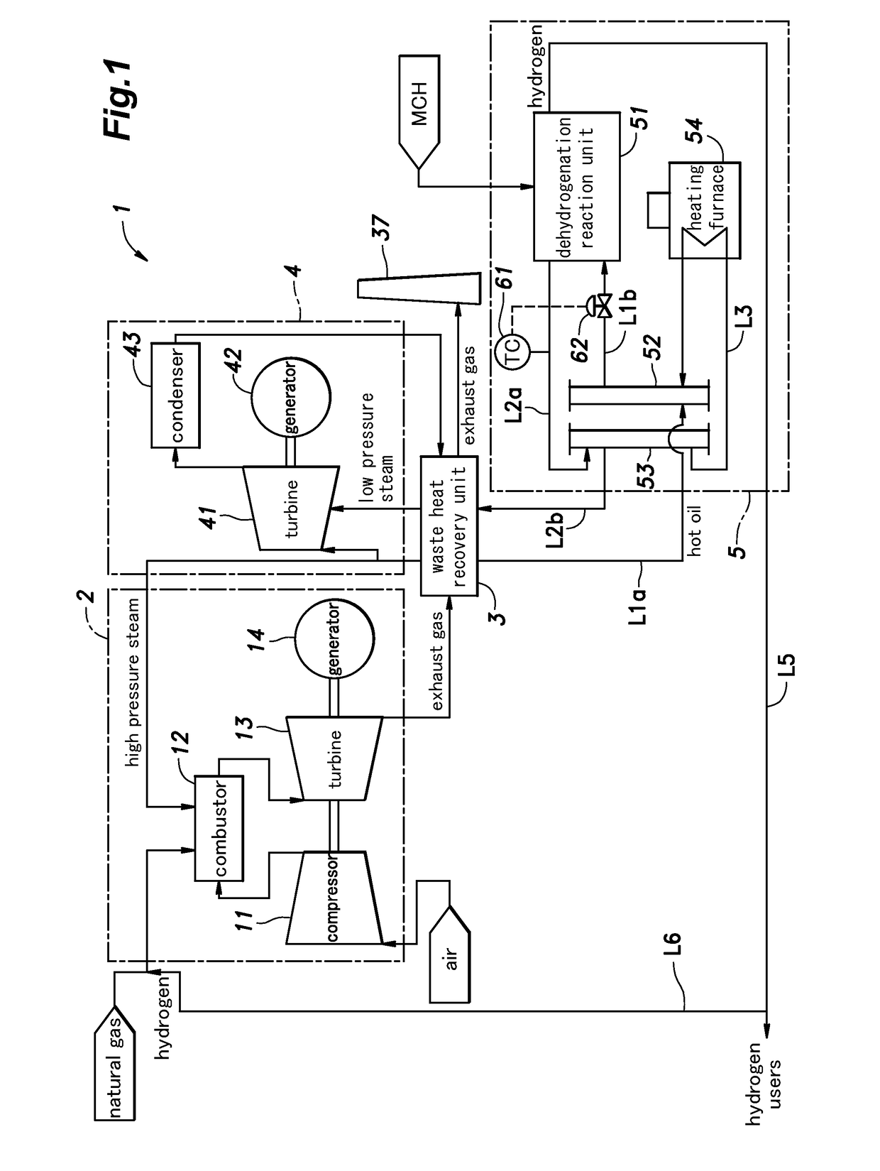
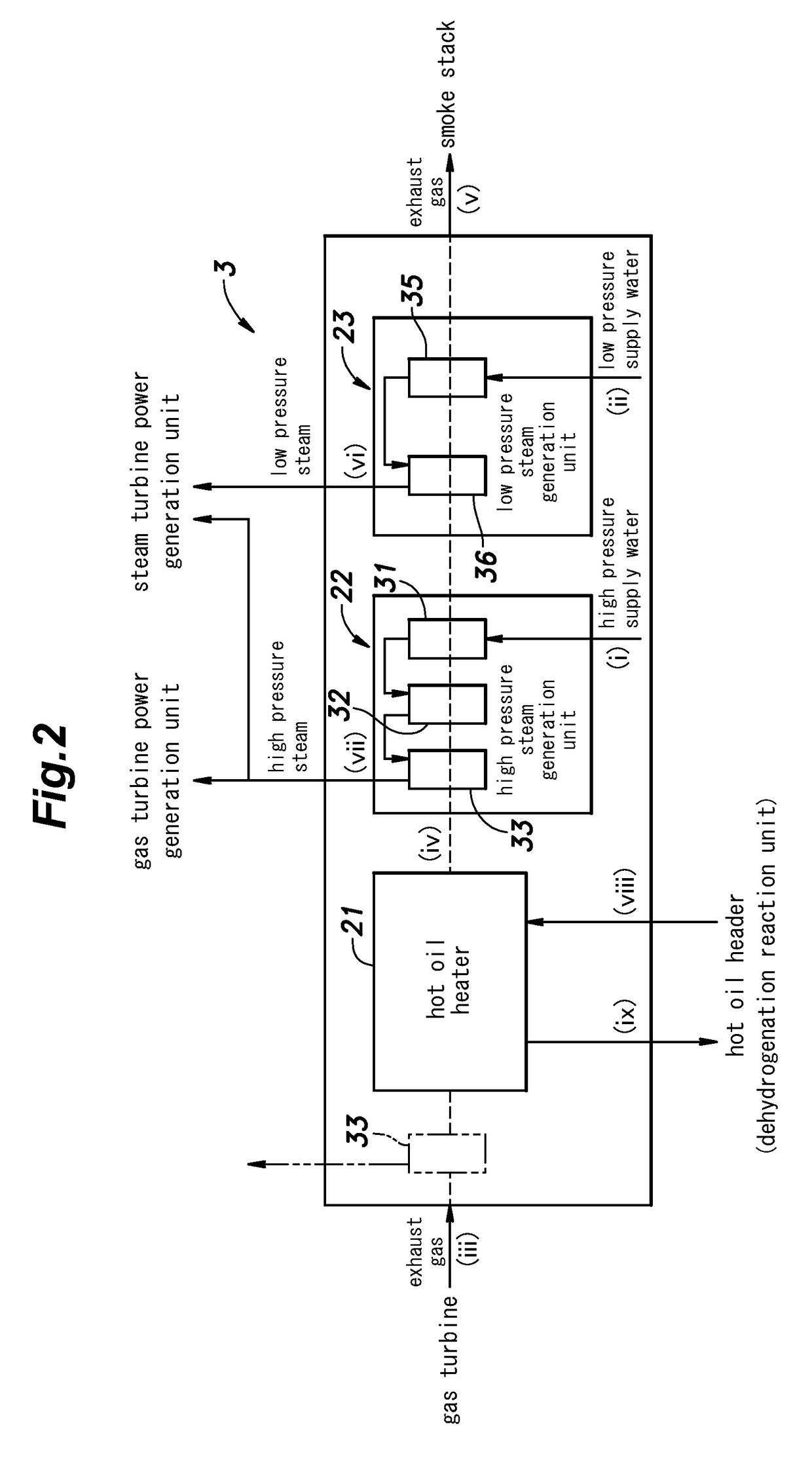
[0027]FIG. 1 is a block diagram showing the simplified overall structure of a hydrogen production system embodying the present invention, and FIG. 2 is a schematic diagram showing the details of the waste heat recovery unit 3 shown in FIG. 1.

[0028]As shown in FIG. 1, the hydrogen production system 1 primarily consists of a gas turbine power generation unit (first power generation unit) 2 for generating electric power from the energy of the combustion gas produced by the combustion of fuel, a waste heat recovery unit 3 for recovering the heat of the exhaust gas expelled from the gas turbine power generation unit 2, a steam power generation unit (second power generation unit) 4 for generating electric power from the energy of the steam generated by the waste heat recovery unit 3 and a hydrogen production unit 5 for producing hydrogen by the dehydrogenation react...


PUM

PropertyMeasurementUnit
temperatureaaaaaaaaaa

Abstract

Provided is a system and a method which allow hydrogen to be produced both efficiently and in a stable manner when using exhaust gas produced by power generation as a heat source for the dehydrogenation reaction, controlling the temperature of the dehydrogenation reaction within an appropriate range. The system (1) for producing hydrogen comprises a dehydrogenation reaction unit (51) for producing hydrogen from an organic hydride by a dehydrogenation reaction in presence of a dehydrogenation catalyst; a first power generation unit (2) for generating electric power from energy of combustion gas produced by combustion of fuel; a waste heat recovery unit (3) for receiving heat from exhaust gas expelled from the first power generation unit; a heat exchanger (21) provided in the waste heat recovery unit for exchanging heat between the exhaust gas and a heat medium; and a circulation line (L1-L3) for introducing the heat medium heated in the heat exchanger to the dehydrogenation reaction unit in liquid form, and returning the heat medium expelled from the dehydrogenation reaction unit to the heat exchanger; wherein the heat medium is introduced into the dehydrogenation reaction unit at an introduction temperature ranging between 352° C. and 392° C., the heat medium is expelled from the dehydrogenation reaction unit at an expulsion temperature ranging between 337 ° C. and 367 ° C., and a difference between the introduction temperature and the expulsion temperature ranges between 10° C. and 50° C.

Description

TECHNICAL FIELD[0001]The present invention relates to a system and a method for producing hydrogen by dehydrogenation of an organic hydride, and in particular to the utilization of the heat that is required for the dehydrogenation reaction.BACKGROUND OF THE INVENTION[0002]The organic chemical hydride process for hydrogenating aromatic compounds such as toluene has recently been developed for the purposes of storing and transporting hydrogen in the form of organic hydrides. According to this process, hydrogen is converted into an organic hydride at the site of hydrogen production, and transported in the form of the organic hydride. The organic hydride is separated into the hydrogen and the aromatic compound at a plant or a hydrogen station located near a city or other user of hydrogen by dehydrogenating the organic hydride. The aromatic compound produced from this dehydrogenation process is transported back to the production site of hydrogen to be hydrogenated by hydrogen once again....

Claims


Application Information

Patent Timeline
Patent Type & Authority Patents(United States)
IPC IPC(8): F02C6/18C01B3/26F02C6/04F23R3/00F01K5/02C10L3/00F02C7/22F01K23/10F02C3/30F02C3/22
CPCF02C3/22C10L3/00F01K5/02F01K23/10F02C3/30F02C6/04F02C6/18F02C7/22F23R3/00C01B3/26Y02P20/129C01B2203/0277C01B2203/0822C01B2203/107C01B2203/1058C01B2203/1064C01B2203/1235C01B2203/1252C01B2203/84Y02E20/14Y02E20/16Y02P20/124Y02P20/10C01B2203/1082
Inventor IKEDA, OSAMUMIKURIYA, TOMOYUKIFURUKAWA, TOSHIKIOZAKI, YUHI
Owner CHIYODA CORP
Why Eureka
Try Eureka