Patch antenna having programmable frequency and polarization

a technology which is applied in the field of programmable frequency and polarization of patch antennas, can solve the problems of deterioration of performance, difficulty in simultaneously reconfiguring the working frequency of the antenna, and not widely used in the field of programming technology of antennas, and achieves the effect of simple feeding network and small siz

Active Publication Date: 2018-12-18
JIANGSU HENGXIN TECH CO LTD
View PDF3 Cites 0 Cited by
  • Summary
  • Abstract
  • Description
  • Claims
  • Application Information

AI Technical Summary

Benefits of technology

[0004]The purpose of the present invention is to provide a patch antenna having programmable frequency and polarization, which can solve the disadvantages of the prior art, including having a big size, complicated feeding network and limited working modes in the prior art.
[0012]Compared with the prior art, the present invention provides a programmable patch antenna having a simple feeding network, small size and various working modes.

Problems solved by technology

However, programming technology has not been widely used in the field of antennas.
However, simultaneously reconfiguring the working frequency of the antenna is difficult because the working frequency of the antenna is mainly determined by the resonance length of the structure.
Although the structural reconfiguration of the antenna can alter the working frequency and polarization, the consequent damage to the structure can cause deterioration of performance and the interference between different working modes that cannot be avoided, resulting in limited choices of working modes, which can be realized by this method.
Nevertheless, both of the two methods have disadvantages of having a big size, complicated feeding way, and use of a large amount of switches.

Method used


Image

  • Patch antenna having programmable frequency and polarization
  • Patch antenna having programmable frequency and polarization

Examples


Embodiment Construction

[0017]Drawings and detailed embodiments are combined hereinafter to elaborate the technical principles of the present invention.

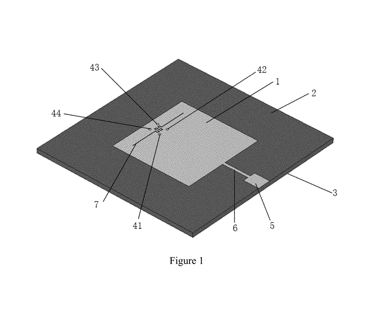
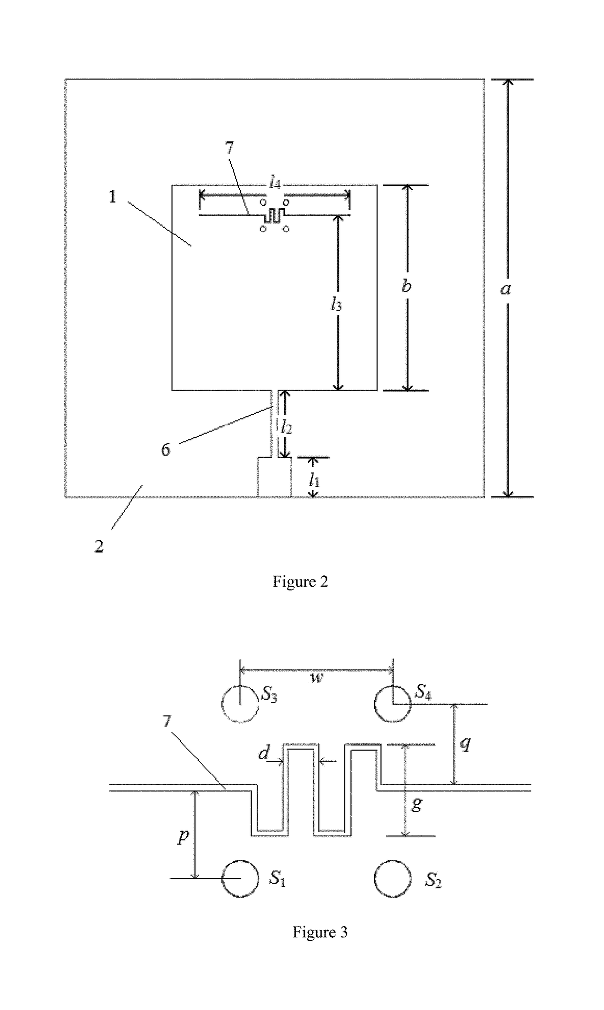
[0018]As shown in FIG. 1, the patch antenna having programmable frequency and polarization comprises the first metal covering layer 1, the dielectric layer 2, the second metal covering layer 3, the first metallized through-hole 41, the second metallized through-hole 42, the third metallized through-hole 43 and the fourth metallized through-hole 44, each which are disposed sequentially from top to bottom. The first metal covering layer 1 comprises the feeding line and the radiating patch. The feeding line comprises the 50Ω micro-strip line 5, which can be connected to the outer feeding port. The micro-strip line 5 is connected to one side of the radiating patch through the high-resistance line 6. The radiating patch is a square-shaped metal patch. A gap 7 is etched near the other side of the radiating patch, namely, the radiating edge. The gap 7 is parallel ...


PUM


Abstract

The present invention relates to a patch antenna having programmable frequency and polarization comprising the first metal covering layer, the dielectric layer, the second metal covering layer and four metallized through-holes, each of which are disposed sequentially from top to bottom, wherein the first metal covering layer comprises the feeding line and the radiating patch; the feeding line comprises the micro-strip line, which can be connected to the outer feeding port; the micro-strip line is connected to one side of the radiating patch through the high-resistance line; the radiating patch is a square-shaped metal patch; a gap is etched near the other side of the radiating patch, namely, the radiating edge; the gap is parallel to the radiating edge.

Description

TECHNICAL FIELD OF THE INVENTION[0001]The present invention relates to the field of antenna technology, and more particularly, to a patch antenna having programmable frequency and polarization.BACKGROUND OF THE INVENTION[0002]With the rapid development of wireless communication systems, the antenna, as a critical component of the system, is required to satisfy a dynamic environment and smaller design space. Therefore, a different design is required to improve the informational capacity and environmental durability of the antenna. The programmable antenna is one potential method of the reconfigurable antenna. The first is to design various working modes on an individual antenna as much as possible, and the second is to choose a working mode through one or more switches. The flexibility of switching among a plurality of working modes can be realized through the programming control of the on-off state. Compared with the conventional reconfigurable antenna, the programmable antenna can ...

Claims


Application Information

Patent Timeline
Patent Type & Authority Patents(United States)
IPC IPC(8): H01Q9/04H01Q9/42
CPCH01Q9/0428H01Q9/0442H01Q9/42H01Q9/0492
Inventor LIN, XIANQIZHANG, JINJIANG, YUANYU, JIAWEIKANG, ZHANYUMEI, PENGLIU, ZHONGHUAHUA, YANPING
Owner JIANGSU HENGXIN TECH CO LTD
Why Eureka
Try Eureka