
Agricultural apparatus and method

a technology of agricultural apparatus and method, applied in the field of agriculture, can solve the problems of labor and equipment, and achieve the effects of reducing workplace accidents, improving inventory control and maintenance, and optimizing the growth and yield of each plan

Active Publication Date: 2018-11-27
JOHNSON GARY LIND +1
View PDF21 Cites 37 Cited by
  • Summary
  • Abstract
  • Description
  • Claims
  • Application Information

AI Technical Summary

Benefits of technology

This patent is about a system for growing and managing agricultural plants in a greenhouse or building using a conveyor system. The conveyor system helps to efficiently move and manage the poles that hold the plants. The system also allows for the use of workers with disabilities in a safer environment compared to field activities. Additionally, the system can improve inventory control, optimize plant growth and yields, and provide just-in-time deliveries of fresh, local, safe, organic produce. The technical effects of the patent include increased efficiency, safety, and the ability to grow and manage plants in a controlled environment while minimizing transportation costs and environmental impacts.

Problems solved by technology

Growing plants on fixed trays or poles require workers to travel to the plants for planting, maintenance, and harvesting, which is labor and equipment intensive.

Method used


Image

  • Agricultural apparatus and method
  • Agricultural apparatus and method
  • Agricultural apparatus and method

Examples


Embodiment Construction

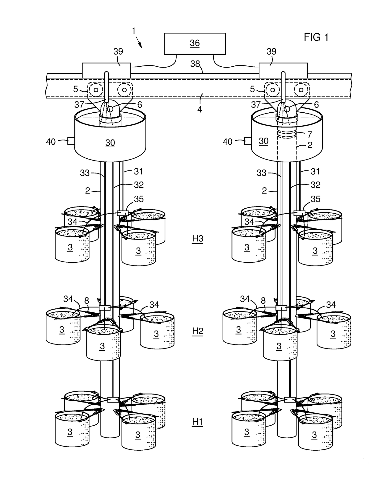
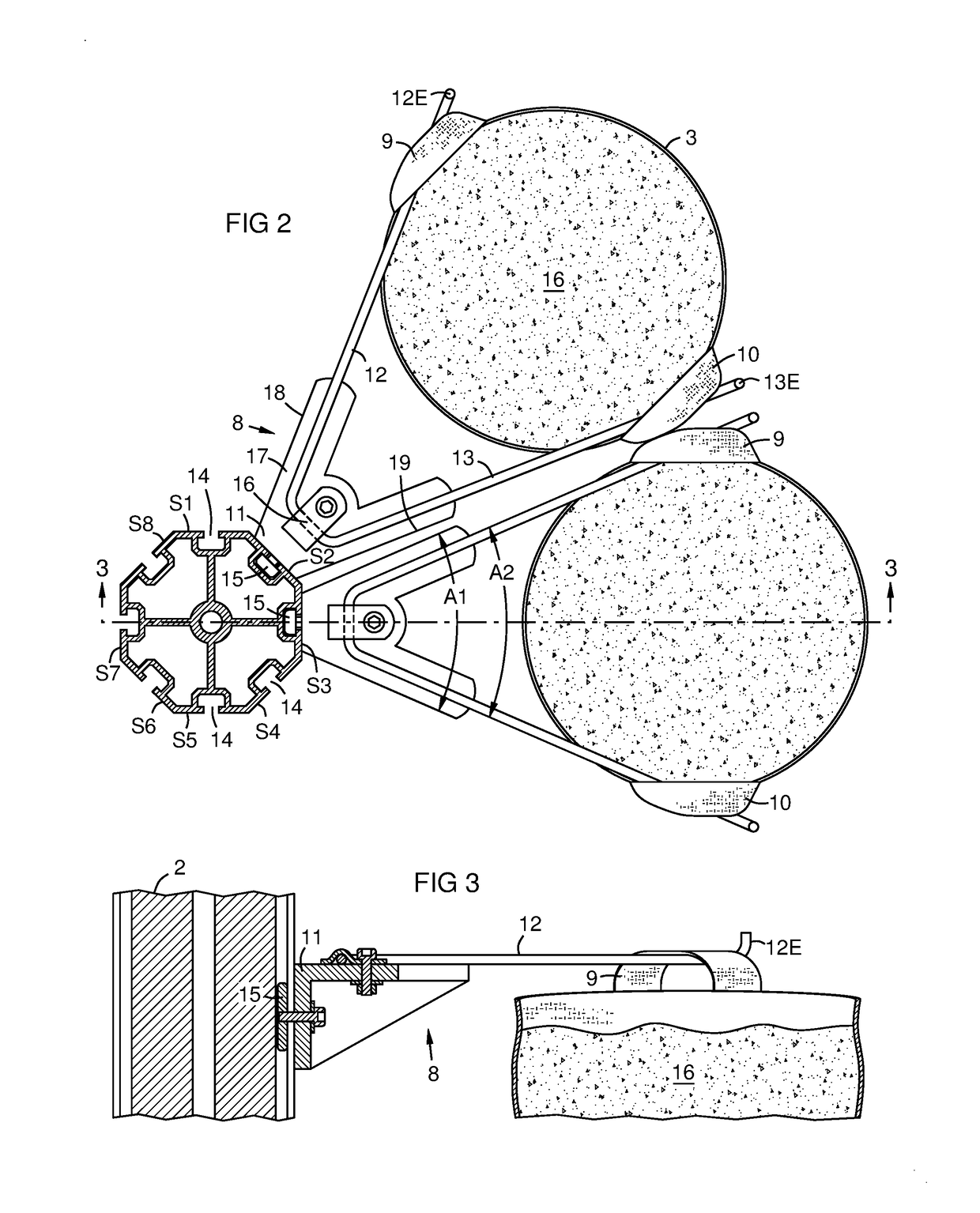
[0016]FIG. 1 illustrates an agricultural apparatus 1 with vertical poles 2 holding plant growing containers 3 at three heights H1, H2, H3 from the pole bottom. An overhead rail 4 provides a conveyor system. Suitable overhead rail types include I-beams, open slotted rails, enclosed rails, inverted rails and hybrid combinations of these or other variations. Each pole is attached to the rail via a trolley 5 that moves along the rail. The trolley may have rollers or slides that move along the rails utilizing a lubricant or magnetic levitation. One type of overhead conveyor system uses a generally rectangular tubular rail with a trolley inside the rail and a load coupler extending downward from the trolley through a slot in the bottom of the rail. Each vertical pole 2 may be attached to a load coupler by a pivot pin 6 that allows the pole to remain vertical regardless of any incline in the rail. Other pole attachment options include a hook or eye attached to the pole and a hook or eye at...


PUM


Abstract

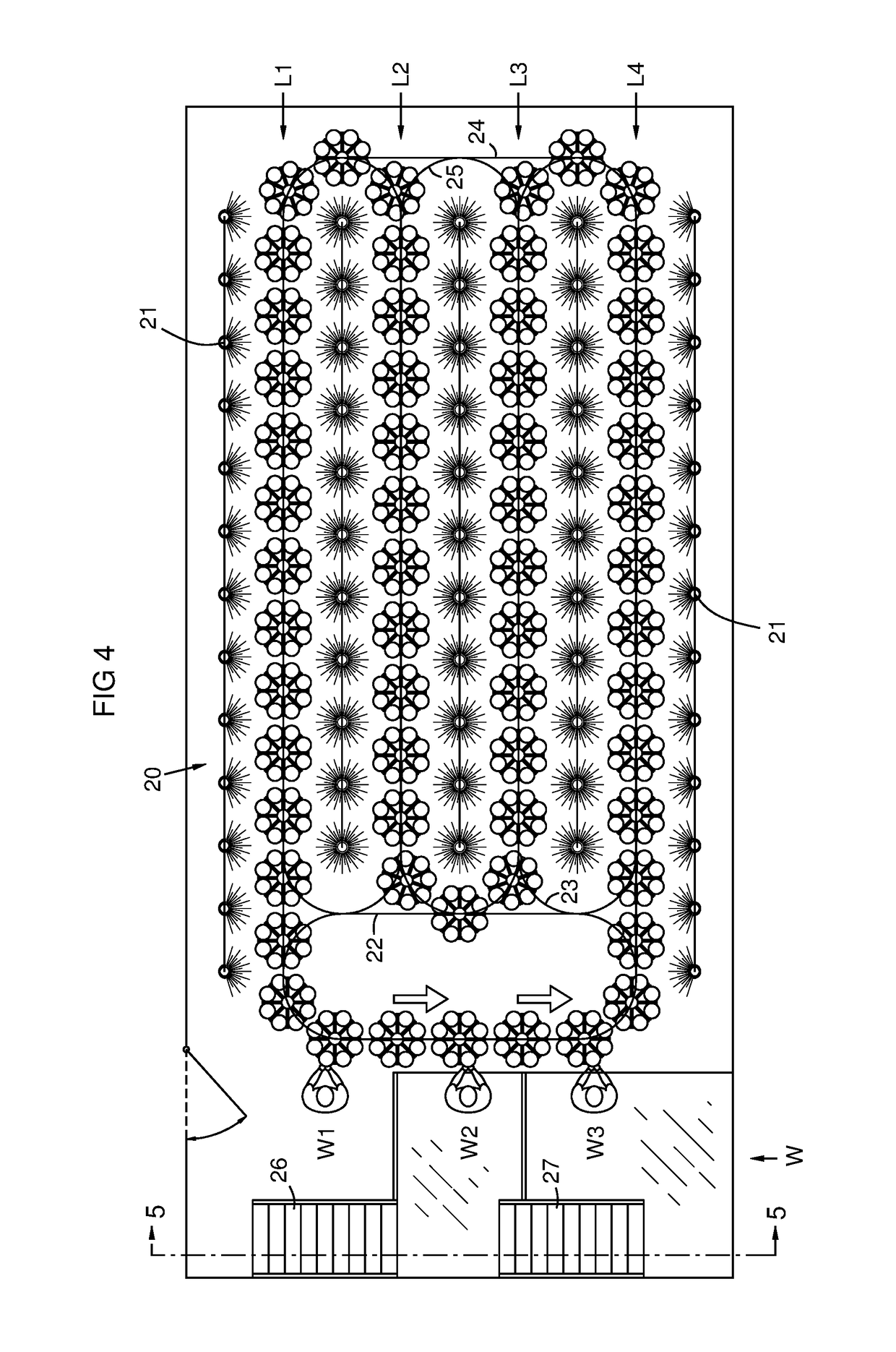
A conveyor system (4, 5) moves vertical poles (2) in an agricultural facility between a growing area (20) and a workstation (W). Each pole carries plant growing containers (3) at multiple levels (H1-H9). An irrigation reservoir (30) may be mounted atop each pole. Irrigation lines (31-33) from the reservoir may be individually metered (35) at each level to compensate for differing water pressure with height. Sensors (40) in the reservoir and at each level of the poles may provide a controller (36) with data input. The controller may impose different growing conditions in different areas of the facility, including vertically different grow areas (20A, 20B), and controls pole movements and locations selectively to provide a sequence of poles at the workstation ready to harvest on a demand schedule. The workstation may have multiple heights (W1, W2, W3) for tall poles that increase plant density per facility footprint.

Description

CROSS-REFERENCE TO RELATED APPLICATIONS[0001]This application claims the benefit of U.S. provisional patent application 62 / 571,437 filed Oct. 12, 2017, which is incorporated herein by reference in its entirety.FIELD OF THE INVENTION[0002]This invention relates generally to the field of agriculture, and in certain embodiments to a process and system for control and management of vertical poles that hold agricultural plants in containers attached to the poles, and which move on a conveyance between a grow area and a workstation for tending.BACKGROUND OF THE INVENTION[0003]Demand for increased food production necessitates innovative approaches to traditional farming models. There are vertical growing systems utilizing hydroponics, aquaponics, or soil to produce vegetables. Growing indoors with grow lights controls the growing environment and protects the plants from insects and diseases, eliminates weather variances, and reduces potential for worker accidents. Growing plants on fixed t...

Claims


Application Information

Patent Timeline
IPC IPC(8): A01G9/02B65G9/00B65G35/06B65G43/08A01G25/09A01G27/00A01G9/24A01G7/04A01G9/20A01G7/02A01G9/18A01G25/16A01G9/08A01G9/14
CPCA01G9/088A01G9/022A01G9/143A01G9/18A01G7/02A01G9/20A01G7/045A01G9/247A01G27/003A01G27/005A01G27/008A01G25/09B65G9/002B65G35/06B65G43/08A01G25/165B65G2203/042B65G2812/182B65G2201/0202B65G2203/0208B65G2203/0283A01G9/023A01G31/045A01G9/249Y02P60/21
Inventor JOHNSON, GARY LINDJOHNSON, KIRK DAVID
Owner JOHNSON GARY LIND
Learn More