
LED illumination device for spotlighting

a technology of led illumination and spotlighting, which is applied in the direction of fixed installation, lighting and heating equipment, lighting support devices, etc., can solve the problems of difficult commercialization increased cost, and relatively high cost of led illumination devices, so as to reduce manufacturing costs, prevent the life of leds from shortening, and high heat dissipation efficiency

Active Publication Date: 2018-11-06
GIGATERA INC
View PDF23 Cites 0 Cited by
  • Summary
  • Abstract
  • Description
  • Claims
  • Application Information

AI Technical Summary

Benefits of technology

The present invention provides an LED illumination device for spotlighting that has a single structure case and components such as a power supply unit, LED-mounted substrates, and a reflector assembled inside the case through a light outlet. The device has high heat dissipation efficiency, preventing shortened lifetime of LEDs due to heat, and prevents damage from heat conduction between the power supply unit and LEDs. The invention reduces manufacturing costs and advances commercialization of the LED illumination device for spotlighting.

Problems solved by technology

However, it is difficult to commercialize such an LED illumination device because an LED itself is very expensive compared to the incandescent or fluorescent lamp and the LED illumination device is relatively expensive since a heat dissipation structure and a power supply unit are separately provided therein.
Hence, the LED illumination device is disadvantageous in that its cost increases due to an increase in production cost, and especially a lot of times and manpower consumed in the assembly processes.

Method used


Image

  • LED illumination device for spotlighting
  • LED illumination device for spotlighting
  • LED illumination device for spotlighting

Examples


Embodiment Construction

[0028]Hereinafter, an LED illumination device for spotlighting according to exemplary embodiments of the present disclosure will be described in detail with reference to the accompanying drawings.

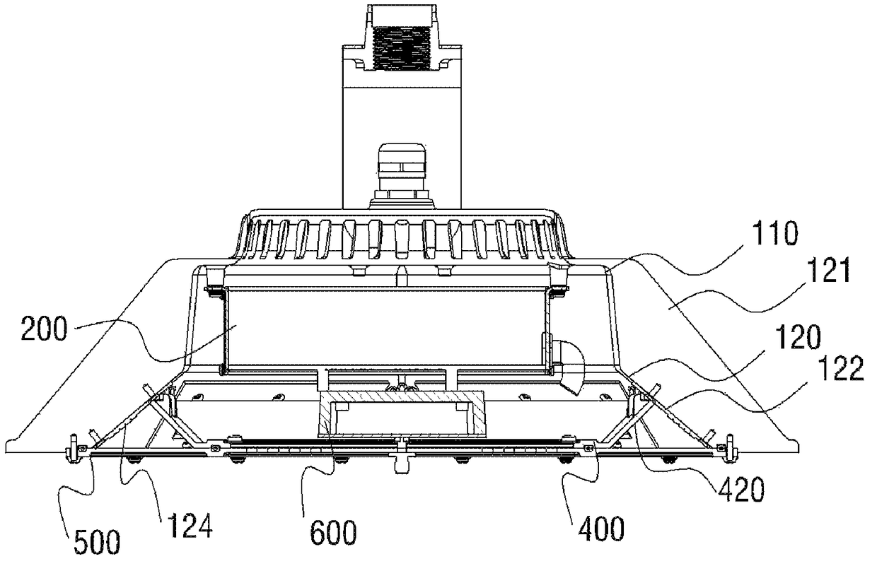
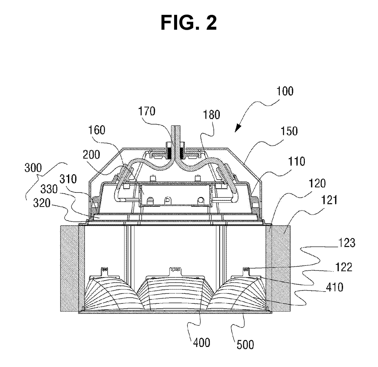
[0029]FIG. 1 is an exploded perspective view illustrating an LED illumination device for spotlighting according to an exemplary embodiment of the present disclosure. FIG. 2 is a cross-sectional view illustrating an assembled state of the LED illumination device in FIG. 1.

[0030]Referring to FIGS. 1 and 2, the LED illumination device for spotlighting according to the embodiment of the present disclosure includes a case 100 that has a light outlet 190 formed on the bottom thereof and includes a longitudinal upper case 110 and a lower case 120 positioned beneath the upper case 110 while having a plurality of inner surfaces as planar installation surfaces, a power supply unit 200 that is fixedly coupled through the light outlet 190 inside the upper case 110 of the case 100, a thermal insulator 3...


PUM


Abstract

An LED illumination device for spotlighting includes: a lower case part having a plurality of planar inner side surfaces so that a light-emitting hole on the bottom surface thereof can be a polygonal shape; an upper case part, positioned above the lower case part, for receiving a power supply unit; substrates which are respectively coupled to the planar inner side surfaces of the lower case part and in which LEDs are mounted such that a light-emitting surface can be directed to the central part of the polygon; and a plurality of heat dissipation fins which are protrudingly positioned along the circumference of the lower case part, wherein the spaces between the heat dissipation fins communicate in the longitudinal direction of the lower case part. A case is manufactured as a single structure and components such as a power supply unit, LED-mounted substrates, reflective plates, etc. can be assembled within the case through the light-emitting hole.

Description

CROSS-REFERENCE TO RELATED APPLICATIONS[0001]This application is a continuation of International Application No. PCT / KR2014 / 012607 filed on Dec. 19, 2014, the entire contents of which are incorporated herein by reference.TECHNICAL FIELD[0002]The present disclosure relates to an LED illumination device for spotlighting, and more particularly, to an LED illumination device for spotlighting, capable of being easily assembled and disassembled and reducing manufacturing costs by minimizing the number of parts.BACKGROUND ART[0003]In recent years, a variety of policies have been proposed to reduce power consumption during the peak time thereof since concerns about blackout are raised in Korea as the power consumption increases. For example, regulations on total energy consumption are enforced for each building to charge a fine if the energy consumption exceeds a reference value, or various methods of changing a lunch break, changing duty uniform regulations, adjusting the service interval ...

Claims


Application Information

Patent Timeline
Patent Type & Authority Patents(United States)
IPC IPC(8): F21V29/76F21V23/02F21V7/04H05B33/08F21V29/505F21V23/00F21V21/14F21S8/00F21Y115/10H05B44/00
CPCF21V29/76F21S8/003F21V7/04F21V21/14F21V23/02F21V29/505H05B33/0845F21V23/001F21Y2115/10F21V7/0008F21V29/15F21Y2107/10H05B45/10
Inventor ROH, DONG-SIKKIM, DUK-YONG
Owner GIGATERA INC
Learn More