
Personal watercraft chassis

a chassis and watercraft technology, applied in the field of personal watercraft chassis, can solve the problems of outpacing the design and manufacturing of watercraft hulls, reducing the service life of watercraft, so as to reduce the manufacturing time, reduce the manufacturing cost, and ensure the stability of the structur

Active Publication Date: 2018-10-23
EMBR MOTORS INC
View PDF35 Cites 2 Cited by
  • Summary
  • Abstract
  • Description
  • Claims
  • Application Information

AI Technical Summary

Benefits of technology

The solution significantly reduces manufacturing costs and time, enhances part consistency and durability, and minimizes environmental impact by enabling a more rigid and modular watercraft design with easier maintenance and replacement of components.

Problems solved by technology

However, conventional watercraft have physical and structural boundaries that are being pushed by enthusiasts every day.
In many cases, the advancement of watercraft engines is outpacing the design and manufacturing of the hulls.
The hulls on conventional watercraft are still manufactured using costly, time-consuming, and environmentally detrimental processes.
The fiberglass manufacturing process is labor-intensive, time-consuming, and releases volatile organic compounds (VOC) that may be toxic to those manufacturing it.
Additionally, the fiberglass fabrication process imposes limitations on the performance, durability, and consistency in the manufacturing of watercraft parts.
This design however does not function alone.
In addition, this current application changes the structure of the vehicle meaning that custom body panels must be made that would not be suitable for watercraft as they would be aesthetic only.
However, the engine still is bolted into the chassis, actually utilizing the motor for structure in frontal collision.
Body panels are also riveted onto the structure for stability, but makes them nearly impossible to remove for maintenance.
This rudimentary practice is time consuming, unreliable, and over time weakens the overall structure of the hull.

Method used


Image

  • Personal watercraft chassis
  • Personal watercraft chassis
  • Personal watercraft chassis

Examples


Embodiment Construction

[0029]Reference will now be made in detail to the example embodiments illustrated in the accompanying drawings. Wherever possible, the same reference numbers will be used throughout the drawings to refer to the same or like parts. Personal watercraft chassis and personal watercraft fabrication using a thermoforming process are described herein.

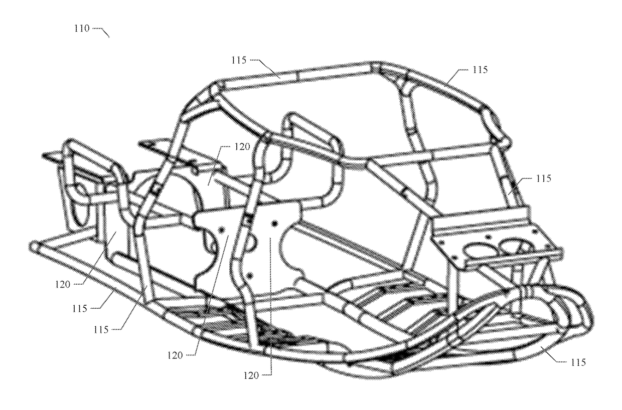
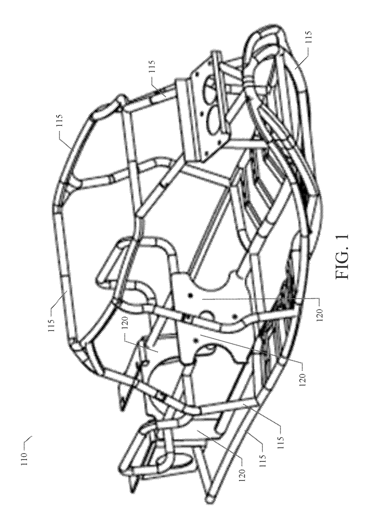
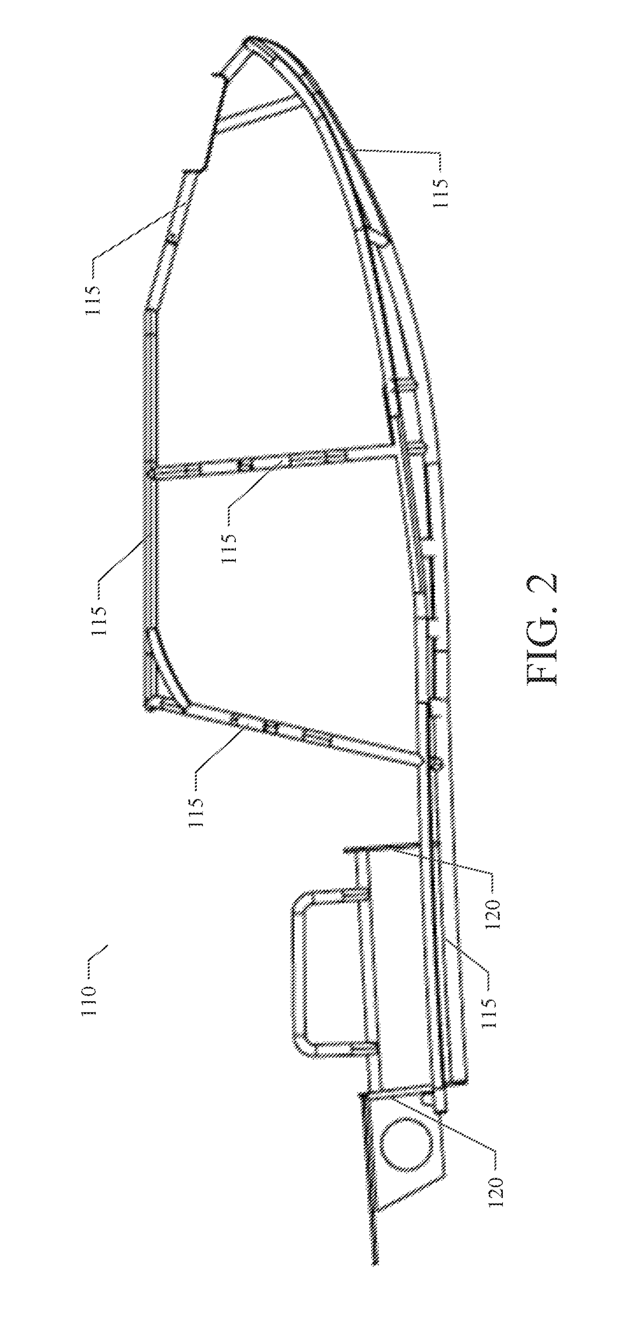
[0030]The Personal Watercraft Chassis 110 of the various example embodiments disclosed herein and shown in FIGS. 1 through 6 allows for the body to be completely independent of the chassis 110 and for the chassis 110) to bolt directly to the motor, but not use the motor for structural means. In the design, an internal skeletal structure fills the internal profile of the hull design, allowing for maximum dispersion of forces. The structure connects only to itself and the body. It does not rely on a frame, sub frame, sheet metal floor, roll cage or additional engine cradle for additional support. The internal profile allows for cross-torsional s...


PUM


Abstract

The various example embodiments disclosed herein pertain to an internal support structure in a watercraft that interfaces the motor to the hull and decreases the weight of the hull, by eliminating various components. The various example embodiments add structural stability to the overall structure of the hull or body, allowing for thinner hull and deck material. This chassis consists of a metal, composite, and or plastic bent or formed tubular structure that outlines the internal dimensions of the hull. The motor is able to mount to this structure so that the body is no longer the direct point of attachment. This furthers the structural stability and reliability of the hull as it disperses forces over a larger area and mounts to a means more suitable than direct hull mounts, which often shear and break loose from the traditional fiberglass hulls. By mounting the engine to this chassis, the hull can be completely removed without disassembling and other components. This allows easier access to the motor and ease of internal maintenance, and allows for replacement hulls and decks when damaged.

Description

PRIORITY PATENT APPLICATION[0001]This is a non-provisional patent application claiming priority to U.S. provisional patent application, Ser. No. 62 / 282,263; filed Jul. 29, 2015. This non-provisional patent application draws priority from the referenced provisional patent application. The entire disclosure of the referenced patent application is considered part of the disclosure of the present application and is hereby incorporated by reference herein in its entirety.TECHNICAL FIELD[0002]The various example embodiments is directed to a fabricated, formed, or assembled chassis, frame or structure, which assists in the structural integrity and assembly of, but not limited to personal watercraft. The “chassis” can be used to assist with the creation of watercraft, including, but not limited to, personal watercraft, jet boats, race dinghies, power surfboards, and other aquatic transportation vehicles.COPYRIGHT[0003]A portion of the disclosure of this patent document contains material tha...

Claims


Application Information

Patent Timeline
Patent Type & Authority Patents(United States)
IPC IPC(8): B63B9/06B63B35/73B63B3/26
CPCB63B35/73B63B3/26B63B34/10
Inventor DARLING, JORDAN
Owner EMBR MOTORS INC
Learn More