
Water turbine propeller

a propeller and water turbine technology, applied in marine propulsion, machine/engine, vessel construction, etc., can solve the problems of high fuel demand for short distance travel, easy wear and breakdown, easy damage, etc., to improve efficiency, improve the speed of transfer, and the effect of improving efficiency

Active Publication Date: 2018-10-16
HAYMAN RICHARD
View PDF15 Cites 0 Cited by
  • Summary
  • Abstract
  • Description
  • Claims
  • Application Information

AI Technical Summary

Benefits of technology

The present invention is a water turbine propeller that is designed to be more efficient and effective in moving large vessels at low speeds. The foil blades create a focused torque effect on the water flow, and the engine that rotates the shaft allows the double helical blades to direct water in one direction and create a vortex effect. This design maximizes thrust and provides better fuel and energy efficiency while propelling the vessel.

Problems solved by technology

However, the design has limited efficiency resulting in high fuel demand for short distance travel.
Other systems may be more efficient in terms of fuel usage, but have other drawbacks such as being prone to wear and breakdown and are easily damaged due to grounding.

Method used


Image

  • Water turbine propeller
  • Water turbine propeller
  • Water turbine propeller

Examples


Embodiment Construction

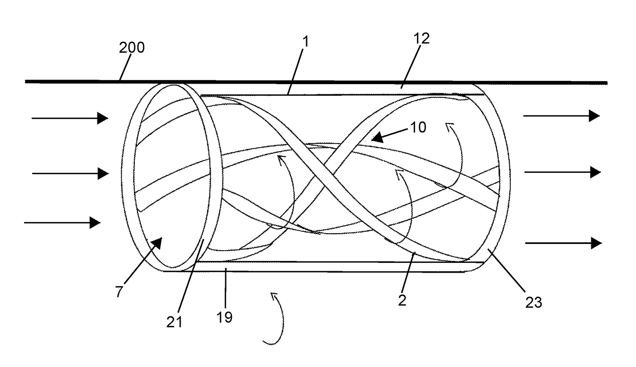
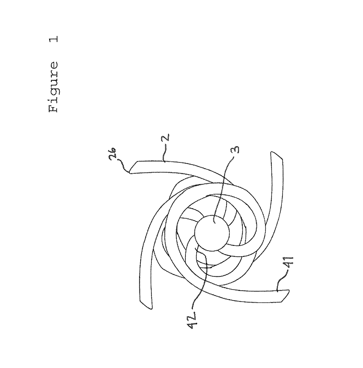
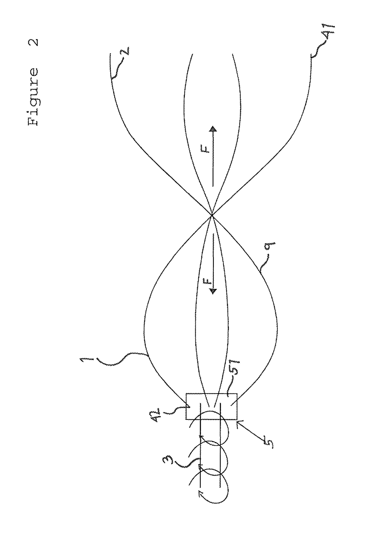
[0026]Referring to FIGS. 1 through 7, there is shown a water turbine propeller apparatus 1 comprising an optional turbine casing 19, a plurality of foil blades 2, and a rotatable shaft 3 having a first mounting surface 51 and a second mounting surface 17. The plurality of foil blades 2 are fixed to the first mounting surface 51. Each foil blade 2 has a leading edge 41 and a trailing edge 42, wherein movement of each blade 2 through a liquid forces the liquid towards the central axis and away from the first mounting surface 51. The present invention further includes a motor 16 that is adapted to rotate the shaft 3 at the second mounting surface 17. Each foil blade 2 attached to the first mounting surface 51 extends outward from the rotatable shaft 3 and circumferentially around a central axis corresponding to the rotatable shaft 3.

[0027]The apparatus 1 is part of a hydro propulsion system that will be most effective at slower rotational speeds and for large vessel propulsion, especia...


PUM


Abstract

A water turbine propeller includes an optional turbine casing having forward and rearward openings, a rotational cylindrical unit, a plurality of rotating foil blades rigidly secured to the inner periphery of the rotational shaft on a common shaft, and an engine or motor which rotates the rotational shaft within the turbine casing. The operation of the engine causes the rotation of the rotational shaft and the helical blades direct water into the forward opening of the turbine casing and out the rearward openings of the turbine casing, thereby creating a focused torque (or vortex) effect on the water flow for a propulsive force.

Description

RELATED APPLICATIONS[0001]The present application claims priority to U.S. Provisional Application No. 61 / 734,410 filed on Dec. 7, 2012, the entire content of which is hereby incorporated by reference.BACKGROUND OF THE INVENTION[0002]1. Field of the Invention[0003]The present invention relates to a marine propulsion system for a watercraft. More particularly, this invention involves a system of rotating foil blades forming a water turbine propeller which generates efficient propulsion at a low rate of revolution.[0004]2. Description of the Related Art[0005]The prior art, as is known to the inventor, consists of turbines, vessels, or marine propulsion system, which conduct water through conduits for propulsion, or actual turbine jets.[0006]U.S. Pat. No. 5,451,137 teaches a reaction turbine and more specifically two unidirectional reaction turbines operable under reversible fluid flows for use with hydro-pneumatic, hydro, wind, or wave power systems. The hydro-pneumatic power systems a...

Claims


Application Information

Patent Timeline
Patent Type & Authority Patents(United States)
IPC IPC(8): B63H1/12B63H1/14B63H1/26F04D3/02
CPCB63H1/12B63H1/14B63H1/26Y02T70/542B63H2001/125F04D3/02Y02T70/50
Inventor HAYMAN, RICHARD
Owner HAYMAN RICHARD
Learn More