
Method and apparatus for determining a constant current limit value

a constant current limit and apparatus technology, applied in secondary cell servicing/maintenance, instruments, electrochemical generators, etc., can solve the problems of irreversible damage to battery cells

Active Publication Date: 2018-09-04
ROBERT BOSCH GMBH
View PDF10 Cites 0 Cited by
  • Summary
  • Abstract
  • Description
  • Claims
  • Application Information

AI Technical Summary

Benefits of technology

[0010]In a method as described above, the constant current limit value is determined by means of the predefined function. In this case, the predefined function is determined depending on the actual correction voltage value. This is done in a simple manner by explicitly taking into account the actual correction voltage value in the first function. It should be taken into consideration here that the actual correction voltage value is determined depending on the measured values of the first current and the first voltage, that is to say depending on actually occurring values of the first current and the first voltage. Therefore, determination of the constant current limit value is not only based on the calculation model which is used for the first profile of the first current, but also on the actually occurring values of the first current and the first voltage. This increases the accuracy of determination of the actual constant current limit value.
[0015]In a method as described above, a degree of accuracy with which the actual constant current limit value is determined is dependent on a degree of accuracy with which the second voltage can be estimated. Furthermore, the degree of accuracy with which the actual constant current limit value is determined is dependent on a degree of accuracy of the calculation model which is used for calculating the first profile of the first current. In this case, the degree of accuracy of the calculation model which is used for calculating the first profile of the first current is dependent, in particular, on a degree of accuracy with which the further parameters can be estimated. It should be taken into consideration here that the second voltage which is applied between the two electrodes of the battery cell can be estimated only inaccurately and changes over the life of the battery cell. It should further be taken into consideration that the actual correction voltage value can be accurately determined. One reason for this is that the actual correction voltage value is dependent on the actually occurring values of the first voltage and the first current which are measured and as a result also accurately determined. Therefore, an inaccuracy with which the second voltage can be estimated and an inaccuracy in the calculation model are compensated for by the actual correction voltage value.
[0019]One advantage of a method as described above is that the constant current limit value can also be used when determining a power limit value by means of which an electrical power of the battery cell can be limited.

Problems solved by technology

It is known from the prior art that battery cells have to be protected against excessively high and excessively low voltage levels since otherwise the service life of the said battery cells is shortened and the battery cells may, under certain circumstances, be irreversibly damaged.

Method used


Image

  • Method and apparatus for determining a constant current limit value
  • Method and apparatus for determining a constant current limit value
  • Method and apparatus for determining a constant current limit value

Examples


Embodiment Construction

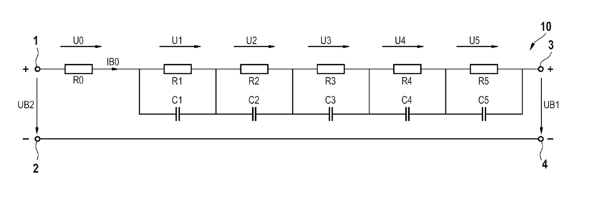
[0026]FIG. 1 shows a predefined equivalent circuit 10 of a battery cell in which a positive battery cell pole 1 and a negative battery cell pole 2 of the battery cell are illustrated, the said battery cell poles being connected to two electrodes of the battery cell 10. A positive terminal 3 and a negative terminal 4 of the battery cell are also illustrated in the equivalent circuit 10. The equivalent circuit 10 comprises a first series circuit which is connected between the positive battery cell pole 1 and the positive terminal 3. The negative battery cell pole 2 is connected to the negative terminal 4 by means of a line.

[0027]The first series circuit comprises a predefined resistor and a second series circuit which are connected in series. The predefined resistor has a resistance value R0.

[0028]The second series circuit comprises, for example, five parallel circuits which have a first, second, third, fourth and fifth parallel circuit which are connected to one another in series. Th...


PUM

PropertyMeasurementUnit
constant currentaaaaaaaaaa
voltageaaaaaaaaaa
currentaaaaaaaaaa

Abstract

A method for determining a constant current limit value by means of which a first current which flows through a battery cell is limited, wherein the constant current limit value is determined on the basis of a first function which specifies a first profile of the first current, which first profile is dependent on a plurality of parameters. The plurality of parameters include a first voltage which is applied between two terminals of the battery cell, a second voltage which specifies a no-load voltage of the battery cell, and a time variable.

Description

BACKGROUND OF THE INVENTION[0001]The present invention relates to a method and an apparatus for determining a constant current limit value by means of which a first current which flows through a battery cell is limited.[0002]It is known from the prior art that battery cells have to be protected against excessively high and excessively low voltage levels since otherwise the service life of the said battery cells is shortened and the battery cells may, under certain circumstances, be irreversibly damaged. Constant current limit values for a first current which flows through a battery cell of this kind are determined for this reason. The said constant current limit values ensure that, when they are complied with, a voltage value of a first voltage remains between suitable voltage limit values. When the first current is flowing, the first voltage is applied between two terminals of the battery cell with which contact can be made from outside the battery cell. The constant current limit ...

Claims


Application Information

Patent Timeline
Patent Type & Authority Patents(United States)
IPC IPC(8): G01R31/36G01R19/165H01M10/42
CPCG01R31/3627G01R19/16542H01M10/42G01R31/3651G01R31/3662G01R31/3624H01M10/44H01M10/48G01R31/367G01R31/3842Y02E60/10G01R31/385G01R31/389
Inventor COIS, OLIVIERZAFIRIDIS, TRIANTAFYLLOS
Owner ROBERT BOSCH GMBH
Learn More