Electrodeless single low power CW laser driven plasma lamp

a low-power, laser-driven, electromechanical technology, applied in the field of illumination devices, can solve the problems of affecting the operation of the lamp, and affecting the operation of the lamp, and achieve the effect of high-intensity ligh

Active Publication Date: 2018-08-21
EXCELITAS TECH
View PDF139 Cites 5 Cited by
  • Summary
  • Abstract
  • Description
  • Claims
  • Application Information

AI Technical Summary

Problems solved by technology

The anode and / or cathode may wear and emit particles.
Such particles can impair the operation of the lamp, and cause degradation of the anode and / or cathode.
Unfortunately, the curved lamp surface distorts the beam of the laser.
A distortion of the beam results in a focal area that is not sharply defined.
While this distortion may be partially corrected by inserting optics between the laser and the curved surface of the lamp, such optics increase cost and complexity of the lamp, and still do not result in a precisely focused beam.
However, use of both a high energy pulsed laser and a lower energy CW laser adds cost, bulk, and complexity to the lamp.

Method used


Image

  • Electrodeless single low power CW laser driven plasma lamp
  • Electrodeless single low power CW laser driven plasma lamp
  • Electrodeless single low power CW laser driven plasma lamp

Examples


first embodiment

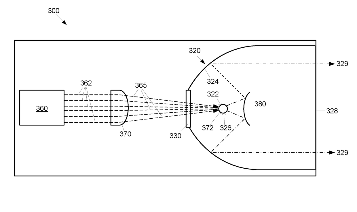
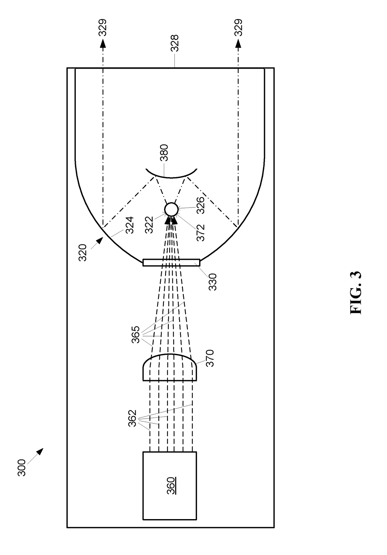
[0029]The high intensity egress light 329 output by the lamp 300 is emitted by a plasma formed of the ignited and energized ionizable medium within the chamber 320. The ionizable medium is ignited within the chamber 320 by one of several means, as described further below, within the chamber 320. The plasma is continuously generated and sustained at a plasma generating and / or sustaining region 326 within the chamber 320 by energy provided by ingress laser light 365 produced by a laser light source 360 located within the lamp 300 and external to the chamber 320. In the first embodiment, the plasma sustaining region 326 is co-located with a focal point 322 of the interior surface 324 at a fixed location. In alternative embodiments the laser light source 360 may be external to the lamp 300.

[0030]The chamber 320 has a substantially flat ingress window 330 disposed within a wall of the interior surface 324. The substantially flat ingress window 330 conveys the ingress laser light 365 into...

third embodiment

[0043]The portion of the chamber 520 where laser light enters the chamber is referred to as the proximal end of the chamber 520, while the portion of the chamber 520 where high intensity light exits the chamber is referred to as the distal end of the chamber 520. For example, in the third embodiment, the ingress window 530 is located at the proximal end of the chamber 520, while the egress window 528 is located at the distal end of the chamber 520.

[0044]Optionally, the third embodiment may include elements for adjusting the pressure level of the sealed chamber 520. The sealed lamp 500 may include a pump system 596 connecting an external source of Xenon gas with the sealed chamber 520 via a fill line 592 connecting the external source of Xenon gas with a gas ingress fill / release valve 594.

[0045]Methods for ignition of Xenon gas / plasma in the chamber 520 may vary depending upon the amount of pressure and / or temperature within the chamber 520, among other factors. At fill pressures bel...


PUM

PropertyMeasurementUnit
Rayleigh lengthaaaaaaaaaa
wavelengthaaaaaaaaaa

Abstract

An ignition facilitated electrodeless sealed high intensity illumination device is configured to receive a laser beam from a continuous wave (CW) laser light source. A sealed chamber is configured to contain an ionizable medium. The chamber has an ingress window disposed within a wall of a chamber interior surface configured to admit the laser beam into the chamber, a plasma sustaining region, and a high intensity light egress window configured to emit high intensity light from the chamber. The CW laser beam is producible by a CW laser below 250 Watts configured to produce a wavelength below 1100 nm. The device is configured to focus the laser beam to a full width at half maximum (FWHM) beam waist of 1-15 microns2 and a Rayleigh length of 6 microns or less, and the plasma is configured to be ignited by the CW laser beam.

Description

CROSS-REFERENCE TO RELATED APPLICATIONS[0001]This application is a continuation-in-part of and claims the benefit of U.S. patent application Ser. No. 14 / 712,304, filed May 14, 2015, entitled “Electrodeless Single CW Laser Driven Xenon Lamp,” which is incorporated by reference herein in its entirety.FIELD OF THE INVENTION[0002]The present invention relates to illumination devices, and more particularly, is related to high intensity lamps.BACKGROUND OF THE INVENTION[0003]High intensity arc lamps are devices that emit a high intensity beam. The lamps generally include a gas containing chamber, for example, a glass bulb, with an anode and cathode that are used to excite the gas within the chamber. An electrical discharge is generated between the anode and cathode to provide power to the excited (e.g. ionized) gas to sustain the light emitted by the ionized gas during operation of the light source.[0004]FIG. 1 shows a pictorial view and a cross section of a low-wattage parabolic prior ar...

Claims


Application Information

Patent Timeline
Patent Type & Authority Patents(United States)
IPC IPC(8): H01J7/24H01J65/04H01J61/54H01J61/02H05H1/46G03F7/20
CPCH05H1/46H01J61/025H01J61/54H01J65/04G03F7/70033G03F7/70008G03F7/70016G03F7/70025G03F7/7005H01J61/16H01J61/30
Inventor BLONDIA, RUDI
Owner EXCELITAS TECH
Why Eureka
Try Eureka