Transmitting apparatus
a technology of transmitting apparatus and receiving apparatus, which is applied in the direction of polarisation/directional diversity, orthogonal multiplex, multiplex communication, etc., to achieve the effect of high data reception quality
- Summary
- Abstract
- Description
- Claims
- Application Information
AI Technical Summary
Benefits of technology
Problems solved by technology
Method used
Image
Examples
first exemplary embodiment
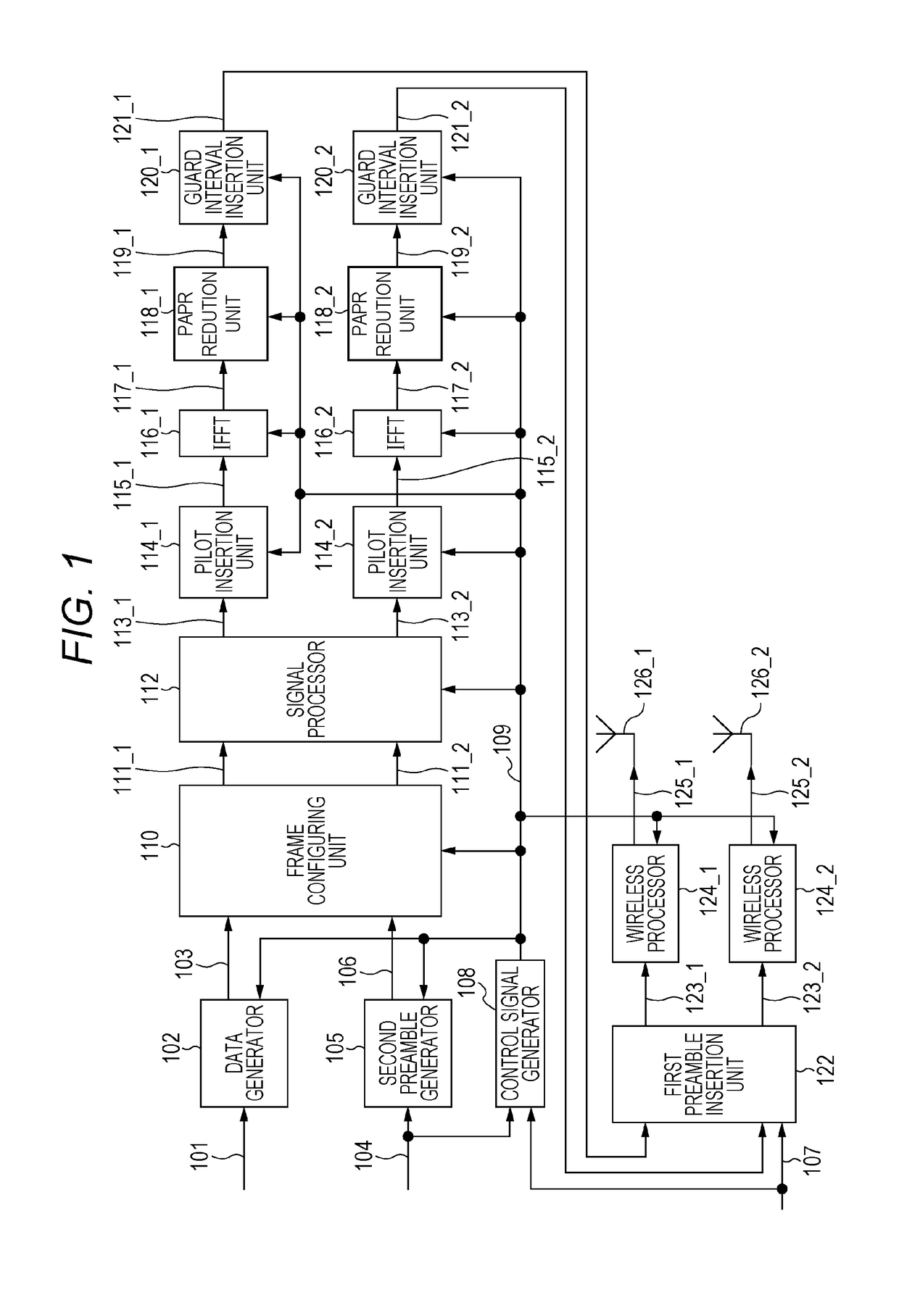
[0089]FIG. 1 is an example of a configuration of a transmitting apparatus (of, for example, a broadcast station) in the present exemplary embodiment.
[0090]Data generator 102 receives an input of transmission data 10801, and control signal 109. Data generator 102 performs error correction coding and mapping which is based on a modulating method, based on information such as information of error correction coding contained in control signal 109 and information of the modulating method contained in control signal 109. Data generator 102 outputs data transmission (quadrature) baseband signal 103.
[0091]Second preamble generator 105 receives an input of second preamble transmission data 104, and control signal 109. Second preamble generator 105 performs error correction coding and mapping which is based on a modulating method, based on information such as information of error correction of a second preamble contained in control signal 109 and information of the modulating method contained...
second exemplary embodiment
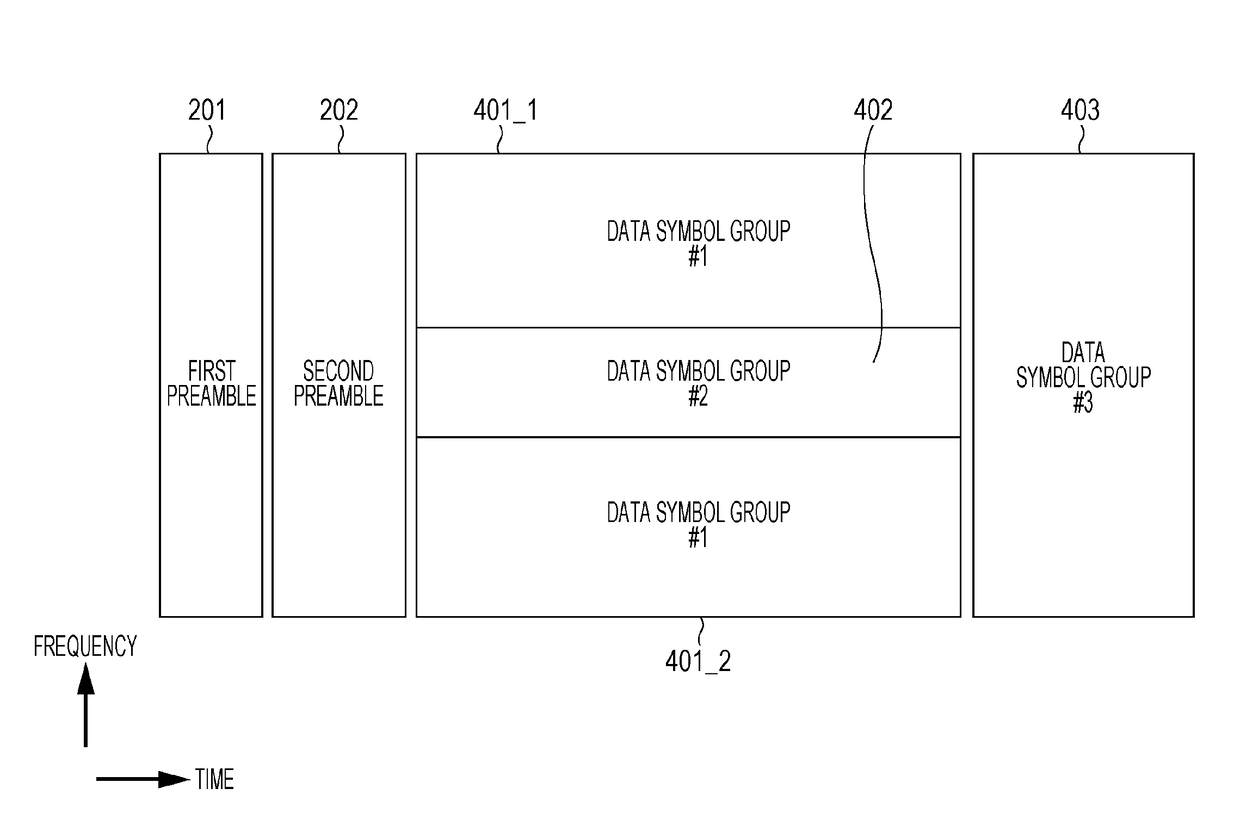
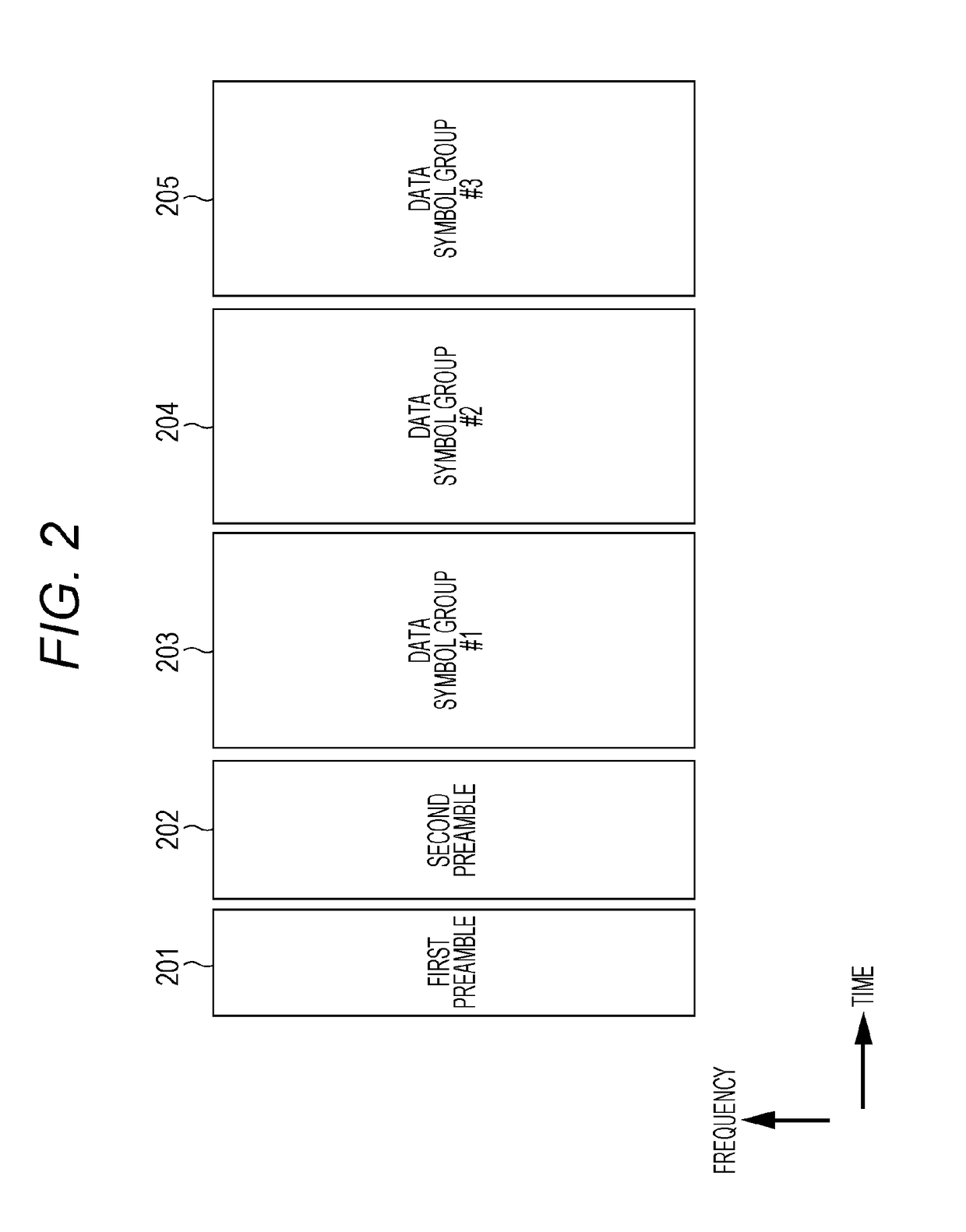
[0300]The first exemplary embodiment describes the case where the transmitting apparatus selects any of the frame configurations in FIGS. 2 to 6 or uses any of the frames in FIGS. 2 to 6. The present exemplary embodiment will describe an example of the method for configuring the first preamble and the second preamble described in the first exemplary embodiment, in the transmitting apparatus described in the first exemplary embodiment.
[0301]As described in the first exemplary embodiment, the transmitting apparatus (FIG. 1) may incorporate “information related to a frame configuration” for transmitting information related to a frame configuration to the receiving apparatus (terminal) in the first preamble or the second preamble, to transmit the “information related to the frame configuration.”
[0302]For example, in a case where the transmitting apparatus transmits a modulated signal with the frame configuration in FIG. 2 when three bits of v0, v1 and v2 are allocated as the “informatio...
third exemplary embodiment
[0501]The first exemplary embodiment and the second exemplary embodiment describe the MIMO transmitting method using precoding and phase change for transmitting a plurality of streams by using a plurality of antennas, or the MIMO transmitting method which does not perform phase change for transmitting a plurality of streams by using a plurality of antennas and the MISO transmitting method using space time block codes or space frequency block codes for transmitting a plurality of streams by using a plurality of antennas. An example of a method for transmitting preambles in a case where it is considered that a transmitting apparatus transmits modulated signals by these transmitting methods will be described.
[0502]The transmitting apparatus in FIG. 1 includes antenna 126_1 and antenna 126_2. In this case, as an antenna configuring method which is highly likely to be easy to demultiplex two modulated signals to be transmitted, there is a method in which “antenna 126_1 is a horizontal po...
PUM
 Abstract
Description
Claims
Application Information
 - R&D
- Intellectual Property
- Life Sciences
- Materials
- Tech Scout
- Unparalleled Data Quality
- Higher Quality Content
- 60% Fewer Hallucinations
Browse by: Latest US Patents, China's latest patents, Technical Efficacy Thesaurus, Application Domain, Technology Topic, Popular Technical Reports.
© 2025 PatSnap. All rights reserved.Legal|Privacy policy|Modern Slavery Act Transparency Statement|Sitemap|About US| Contact US: help@patsnap.com


