
Integrated circuit

a circuit and integrated circuit technology, applied in the field of transmission apparatus, to achieve the effect of improving the quality of data reception

Active Publication Date: 2021-06-03
PANASONIC INTELLECTUAL PROPERTY CORP OF AMERICA
View PDF0 Cites 0 Cited by
  • Summary
  • Abstract
  • Description
  • Claims
  • Application Information

AI Technical Summary

Benefits of technology

The patent text describes a transmission device that can send identical signals to multiple users using the same times and frequencies. This avoids the issue of poor reception caused by direct waves and improves the data quality for the reception device. In brief, this technology helps ensure that each user has a good signal quality, even in environments where direct waves are dominant.

Problems solved by technology

However, the transmission apparatus in FIG. 33 does not consider transmitting modulated signals to multiple terminals (multiple users) using identical times and identical frequencies (identical frequency bands).

Method used


Image

  • Integrated circuit
  • Integrated circuit
  • Integrated circuit

Examples


example 1

[0446]In a case where the terminal #p transmits the data 3001 set to “01” (i.e., “communication scheme #A” is supported), the base station (AP) that has obtained the data determines that the data 3003 is invalid because “error-correcting coding scheme #D” is not selectable in “communication scheme #A”. When generating modulated signals addressed to the terminal #p, the base station (AP) performs error-correcting coding by using “error-correcting coding scheme #C”.

example 2

[0447]In a case where the terminal #p transmits the data 3001 set to “01” (i.e., “communication scheme #A” is supported), the base station (AP) that has obtained the data determines that the data 2801 and the data 2901 are invalid because the “scheme for transmitting multiple modulated signals including multiple streams by using multiple antennas” is not supported in “communication scheme #A”. When generating modulated signals addressed to the terminal, the base station (AP) generates a modulated signal of a single stream and transmits it.

[0448]In addition to the above, a case with the following constraints will be discussed.

Constraint condition 1: In “communication scheme #B”, it is assumed that, in the single-carrier scheme, in the “scheme for transmitting multiple modulated signals including multiple streams by using multiple antennas”, the scheme for “performing phase change on at least one modulated signal among multiple modulated signals” is not supported (other schemes may be...

example 3

[0450]In a case where the terminal #p transmits the data 3002 set to “01” (i.e., only the single-carrier scheme is supported), the base station (AP) that has obtained the data determines that the data 2801 is invalid. When generating modulated signals addressed to the terminal #p, the base station (AP) does not use the scheme for “performing phase change on at least one modulated signal among multiple modulated signals”.

[0451]FIG. 30 is an example of the reception capability notification symbol 2702 transmitted by the terminal #p. As described above by using FIG. 30, in a case where the terminal #p transmits multiple pieces of reception capability information (for example, the data 2801, the data 2901, the data 3001, the data 3002, and the data 3003 in FIG. 30), the base station (AP) may need to determine that some of the multiple pieces of reception capability information are invalid when deciding a method for generating modulated signals addressed to the terminal #p on the basis o...


PUM


Abstract

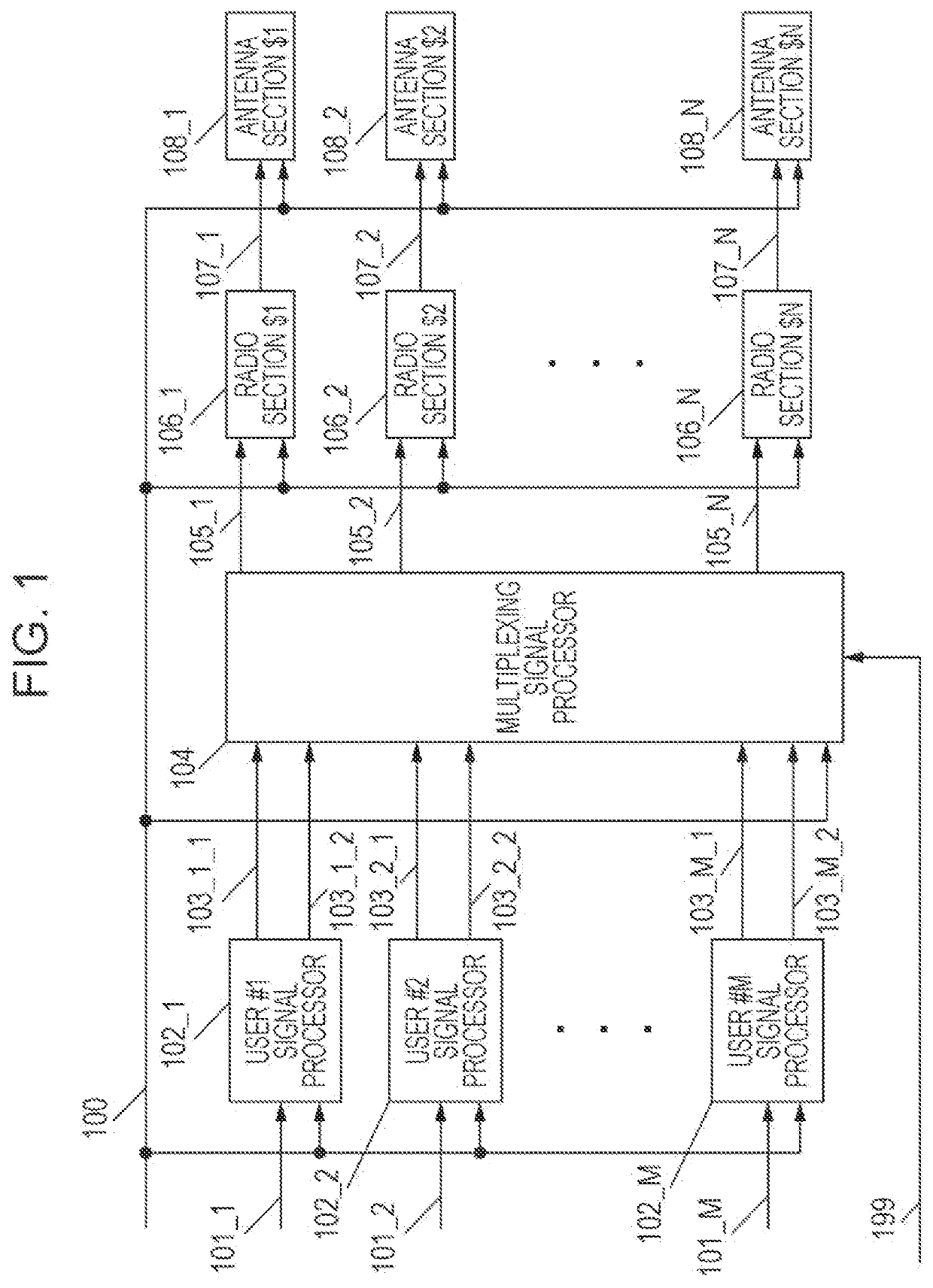
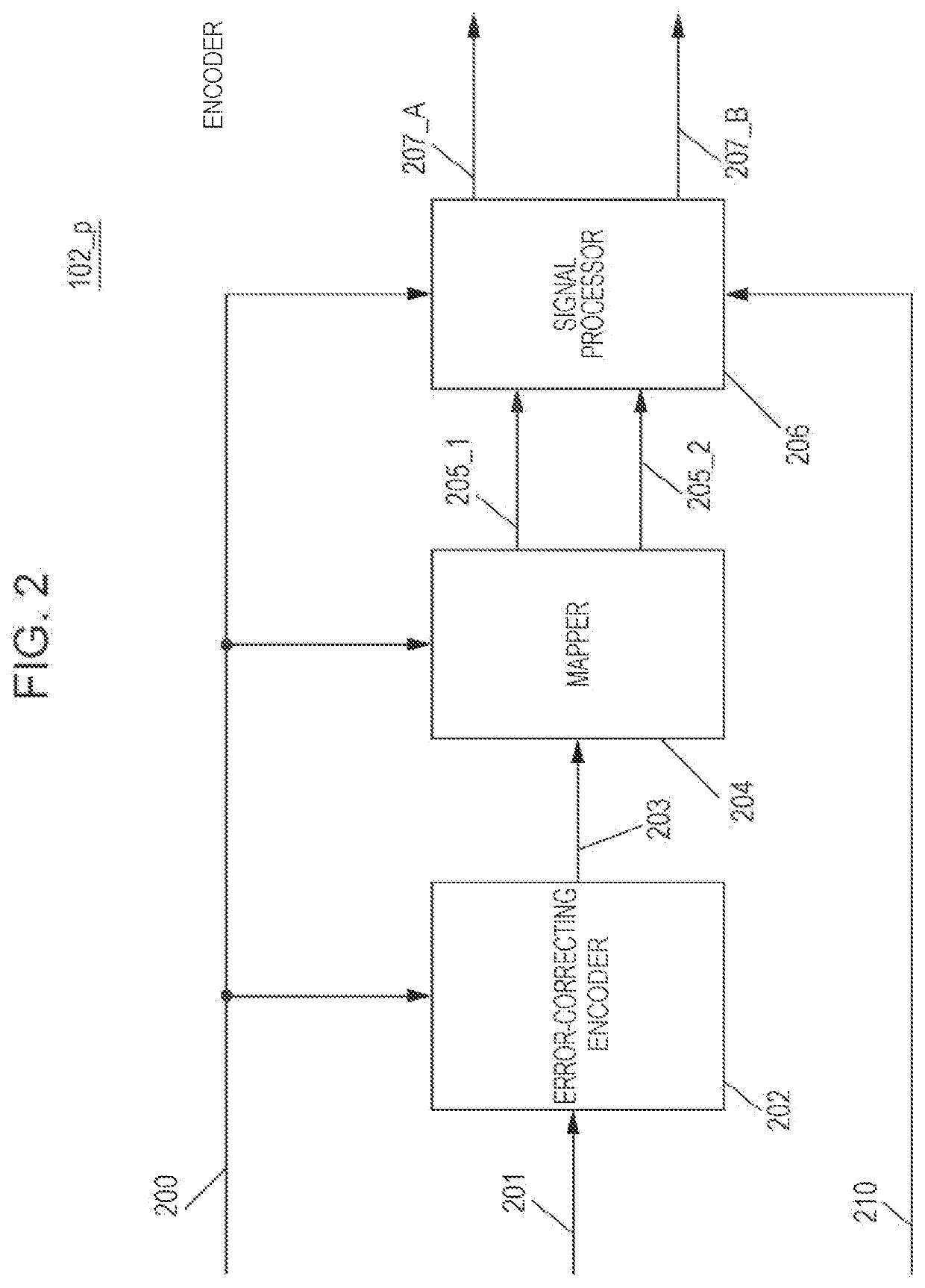
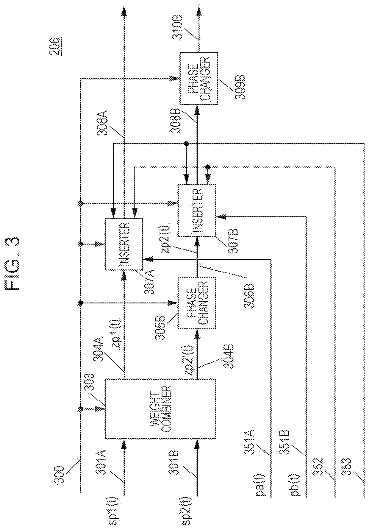
A transmission apparatus includes M signal processors that respectively generate modulated signals directed to M reception apparatuses, M being an integer equal to or greater than 2, and an antenna section. Each signal processor modulates a first bit sequence made up of two bits to generate a first modulated signal and a second modulated signal, and modulates a second bit sequence made up of other two bits to generate a third modulated signal and a fourth modulated signal, in a case of transmitting multiple streams to a corresponding one of the M reception apparatuses. The antenna section includes a first antenna that transmits the first modulated signal and the third modulated signal and a second antenna that transmits the second modulated signal and the fourth modulated signal. At least either the signals transmitted from the first antenna or the signals transmitted from the second antenna are phase-changed signals.

Description

BACKGROUND1. Technical Field[0001]The present disclosure relates to a transmission apparatus and a transmission method.2. Description of the Related Art[0002]A communication method called Multiple-Input Multiple-Output (MIMO), for example, is known as a communication method using multiple antennas. In multi-antenna communication for a single user represented by MIMO, multiple sequences of transmission data are individually modulated, modulated signals obtained accordingly are simultaneously transmitted from different antennas, and thus the data communication speed is increased.[0003]FIG. 33 is a diagram illustrating an example of the configuration of a transmission apparatus that is based on the Digital Video Broadcasting-Next Generation Handheld (DVB-NGH) standard in a case where the number of transmission antennas is two and the number of modulated transmission signals (transmission streams) is two, which is described in “MIMO for DVB-NGH, the next generation mobile TV broadcastin...

Claims


Application Information

Patent Timeline
Patent Type & Authority Applications(United States)
IPC IPC(8): H04B7/06H04B7/0452H04L1/06H04L1/00H04B7/0456
CPCH04B7/0682H04B7/0452H04L1/0618H04L27/2602H04B7/0456H04B7/0697H04L1/0003H04B7/0613H04B7/0602H04L27/2626H04L27/0008H04B7/06H04L27/26H04B1/707Y02D30/70H04B2201/70703
Inventor MURAKAMI, YUTAKAKIMURA, TOMOHIROOUCHI, MIKIHIRO
Owner PANASONIC INTELLECTUAL PROPERTY CORP OF AMERICA
Learn More