Cooling apparatus for internal combustion engine

a technology for internal combustion engines and cooling apparatuses, which is applied in mechanical apparatus, machines/engines, engine starters, etc., can solve the problems of controllability deterioration of cooling apparatuses, and suppress the deterioration of cooling apparatus controllability when the internal combustion engine is restarted

Inactive Publication Date: 2018-08-21
TOYOTA JIDOSHA KK
View PDF26 Cites 2 Cited by
  • Summary
  • Abstract
  • Description
  • Claims
  • Application Information

AI Technical Summary

Benefits of technology

[0010]Embodiments of the present invention address the above described problem, and an object of embodiments of the present invention is to provide a cooling apparatus for an internal combustion engine that can suppress a deterioration in the controllability of a cooling apparatus that is caused by short-time engine stopping in an internal combustion engine in which automatic stopping for a short time and restarting of the engine is performed.
[0037]According to the seventh embodiment of the present invention, a deterioration in the controllability of the cooling apparatus can be suppressed during automatic stopping and a time of restarting in accordance with idling stop-and-start control.

Problems solved by technology

Here, time is required until the state of cooling water that flows through the engine cooling water circulation circuit becomes an intended state, and consequently there is a concern that the controllability of the cooling apparatus will deteriorate.

Method used


Image

  • Cooling apparatus for internal combustion engine
  • Cooling apparatus for internal combustion engine
  • Cooling apparatus for internal combustion engine

Examples


first embodiment

Specific Processing in First Embodiment

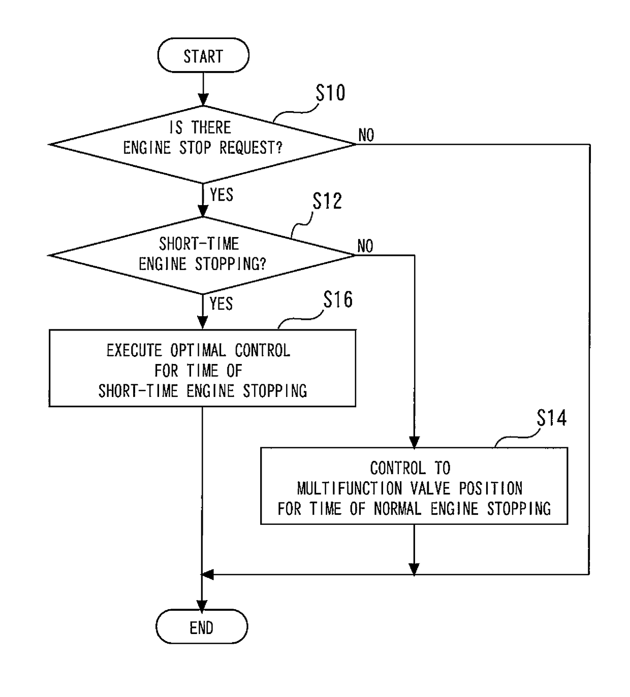
[0073]Next, specific processing of the valve control that is executed in the cooling apparatus of the present embodiment will be described. FIG. 4 is a flowchart illustrating a control flow of the valve control by the ECU 40. The ECU 40 repeatedly executes a routine represented by this control flow at predetermined control periods that correspond to the clock speed of the ECU.

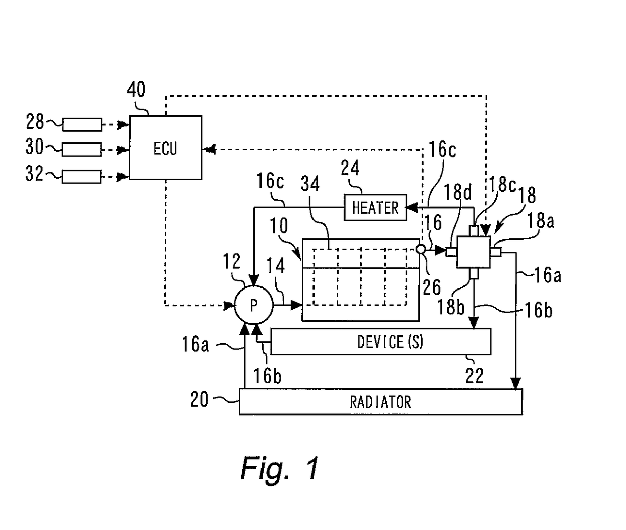
[0074]In a routine shown in FIG. 4, first, the ECU 40 determines whether or not there is an engine stop request (step S10). If it is determined as a result that there is not an engine stop request, the present routine is ended. On the other hand, if it is determined in the aforementioned step S10 that there is an engine stop request, the operation shifts to the next step in which the ECU 40 determines whether the current state is a state in which a request to perform short-time engine stopping is being executed (step S12). Specifically, the ECU 40 determines whether or not...

second embodiment

Specific Processing in Second Embodiment

[0087]Next, specific processing of the valve control that is executed in the cooling apparatus of the present embodiment will be described. FIG. 5 is a flowchart illustrating a control flow of optimal control during short-time engine stopping that is executed by the ECU 40. The routine illustrated in FIG. 5 is executed when the processing in step S14 of the routine illustrated in the aforementioned FIG. 4 is performed.

[0088]According to the routine illustrated in FIG. 5, first, it is determined whether or not temperature control is being executed (step S20). If it is determined as a result that temperature control is not being executed, the operation transitions to the next step to retain the rotation angle of the rotor of the multifunction valve 18 at the position thereof immediately prior to engine stopping (step S22).

[0089]On the other hand, if it is determined by the processing in the aforementioned step S20 that temperature control is bei...


PUM


Abstract

A cooling apparatus includes a coolant circulation channel for returning a coolant that passes through an engine main body, after causing the coolant to exchange heat with a radiator, device(s) and a heater, respectively. A multifunction valve as a rotary valve that is capable of adjusting an amount of coolant that is circulated to the radiator, device(s) and heater, respectively, is disposed in the coolant circulation channel. When automatic stopping of the engine is performed by idle stop-start control, during the automatic stopping the control apparatus continues to execute valve control of the multifunction valve that is being executed during the operation before the start of the automatic stopping.

Description

CROSS-REFERENCE TO RELATED APPLICATION[0001]The present application claims priority to Japanese Patent Application No. 2015-125567 filed on Jun. 23, 2015, which is incorporated herein by reference in its entirety.TECHNICAL FIELD[0002]Embodiments of the present invention relate to a cooling apparatus for an internal combustion engine.BACKGROUND[0003]Japanese Patent No. 4755572 discloses a system that includes a heat accumulator for storing / circulating engine cooling water in an engine cooling water circulation circuit that connects an engine and a heater core of an air-conditioning unit. An engine-side valve is disposed in a communication portion between an outlet / inlet on the engine side and an inlet on the heat accumulator side in the engine cooling water circulation circuit. Further, a heater-side valve is disposed in a communication portion between an outlet / inlet on the heater core side and an outlet on the heat accumulator side.[0004]In the system disclosed in Japanese Patent N...

Claims


Application Information

Patent Timeline
Patent Type & Authority Patents(United States)
IPC IPC(8): F01P7/14F01P7/16F02N11/08F01P5/12B60W30/18
CPCF01P7/16F01P5/12F01P7/167F02N11/0814B60W30/18018F02N11/0829F01P2037/02F01P2060/04F01P2060/045F01P2060/16F01P2007/146F01P3/20F01P7/162F01P7/164F01P7/165
Inventor WATANABE, HIROSHI
Owner TOYOTA JIDOSHA KK
Why Eureka
Try Eureka