
Motor structure for variable counter electromotive force

a technology of counter electromotive force and motor structure, which is applied in the direction of dynamo-electric components, dynamo-electric machines, magnetic circuit shapes/forms/construction, etc., can solve the problems of difficult control, increase in motor manufacturing cost, and decrease in efficiency and output, so as to reduce interlinkage flux, increase output, and motor efficiency

Active Publication Date: 2018-08-14
HYUNDAI MOTOR CO LTD
View PDF14 Cites 2 Cited by
  • Summary
  • Abstract
  • Description
  • Claims
  • Application Information

AI Technical Summary

Benefits of technology

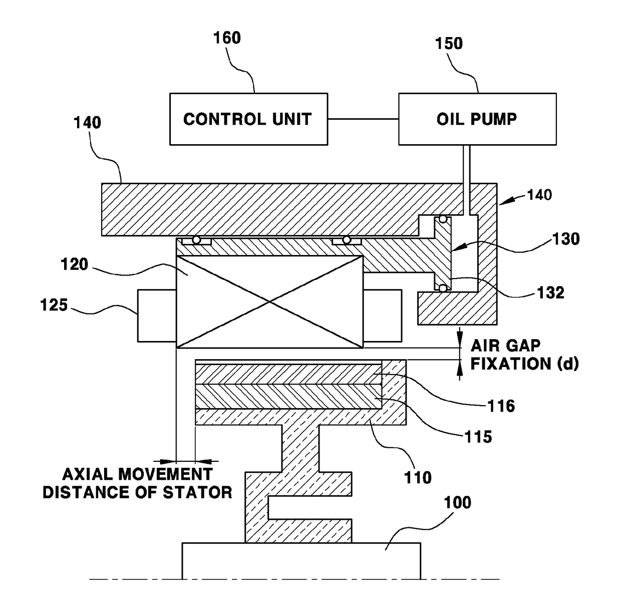
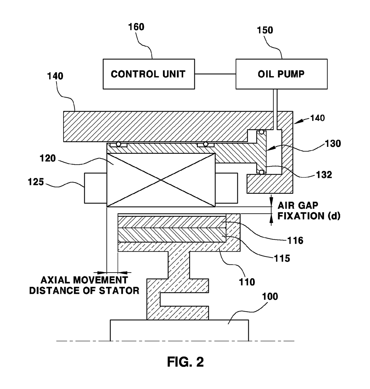
[0011]The present invention provides a motor structure for variable counter electromotive force that improves motor efficiency in a high rotation region by moving a stator support in an axial direction of the motor in an interior rotor structure to reduce a passage area of interlinkage flux of the stator and reduce the counter electromotive force.
[0016]According to the present invention, the stator support portion may move forward or backward in an axial direction based on the normal and reverse rotation of the motor. Additionally, an area in which the magnetic flux of the permanent magnet of the rotor fixed on the exterior circumferential surface of the shaft passes through the coil may be reduced, and the interlinkage flux is reduced. Accordingly, the counter electromotive force reduction of the motor may be controlled and motor efficiency and an increase in output in a high rotation region.

Problems solved by technology

However, such method produces a decrease in efficiency and output since it is necessary to supply current independent of torque to control the weak flux.
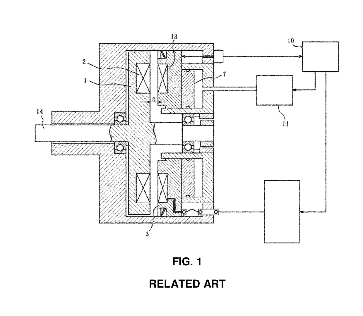
However, the motor of the prior art described above causes an increase in a manufacturing cost of the motor and is problematic and difficult to control.

Method used


Image

  • Motor structure for variable counter electromotive force
  • Motor structure for variable counter electromotive force
  • Motor structure for variable counter electromotive force

Examples


Embodiment Construction

[0024]Hereinafter reference will now be made in detail to embodiments of the present invention, examples of which are illustrated in the accompanying drawings and described below. While the invention will be described in conjunction with exemplary embodiments, it will be understood that present description is not intended to limit the invention to those exemplary embodiments. On the contrary, the invention is intended to cover not only the exemplary embodiments, but also various alternatives, modifications, equivalents and other embodiments, which may be included within the spirit and scope of the invention as defined by the appended claims.

[0025]The terminology used herein is for the purpose of describing particular embodiments only and is not intended to be limiting of the invention. As used herein, the singular forms “a”, “an” and “the” are intended to include the plural forms as well, unless the context clearly indicates otherwise. It will be further understood that the terms “c...


PUM


Abstract

A motor structure for varying a counter electromotive force is provided. The motor structure includes a rotor that is fixed annularly and concentrically to a radially outside from an exterior circumferential surface of a shaft of an electric motor and has a permanent magnet, and a stator that has coils positioned on the interior side of a motor housing and on the concentrically exterior side with the permanent magnet of the rotor. Further, the coils are positioned spaced apart from each other at predetermined intervals. A drive unit moves the stator in the axial direction of the shaft to vary the interlinkage flux, by varying an area that the magnetic flux of the permanent magnet of the rotor passes through the coils of the stator.

Description

CROSS-REFERENCE TO RELATED APPLICATION[0001]This application claims under 35 U.S.C. § 119(a) the benefit of Korean Patent Application No. 10-2015-0083958 filed on Jun. 15, 2015, the entire contents of which are incorporated herein by reference.BACKGROUND(a) Technical Field[0002]The present disclosure relates to a motor structure capable of varying the counter electromotive force and more particularly, to an improved structure by controlling an area in which magnetic flux of a permanent magnet reaches a core of a stator to suppress the counter electromotive force at a high rotational speed of a motor in an electric vehicle.(b) Background Art[0003]Recently, due to the adverse effect of environment caused by air pollution and depletion of fossil fuel, hybrid vehicles and electric vehicles have been developed. The hybrid vehicles utilize an internal combustion engine as a primary power source and utilize an electric motor as an auxiliary power source, and the electric vehicles are types...

Claims


Application Information

Patent Timeline
Patent Type & Authority Patents(United States)
IPC IPC(8): H02K21/00H02K21/02H02K1/28H02K41/00H02K17/30
CPCH02K21/024
Inventor YIM, JEONG BINJEON, JAE HWAHAN, DEA WOONGLEE, SANG KYU
Owner HYUNDAI MOTOR CO LTD
Learn More