Eureka AIR delivers breakthrough ideas for toughest innovation challenges, trusted by R&D personnel around the world.

Polarized light source device

a light source and polarization technology, applied in the field of light sources, can solve the problems of more than 50% of light emitted by the light source being lost, energy loss, and further intensification of the problem

Inactive Publication Date: 2018-07-31
YISSUM RES DEV CO OF THE HEBREWUNIVERSITY OF JERUSALEM LTD +1
View PDF11 Cites 1 Cited by
  • Summary
  • Abstract
  • Description
  • Claims
  • Application Information

AI Technical Summary

Benefits of technology

[0023]There is a need in the art in a novel approach for configuring a polarized light source based on emitting nanostructures for maximizing polarization of light interacting with the nanostructures as well as for maximizing output efficiency of the polarized light.
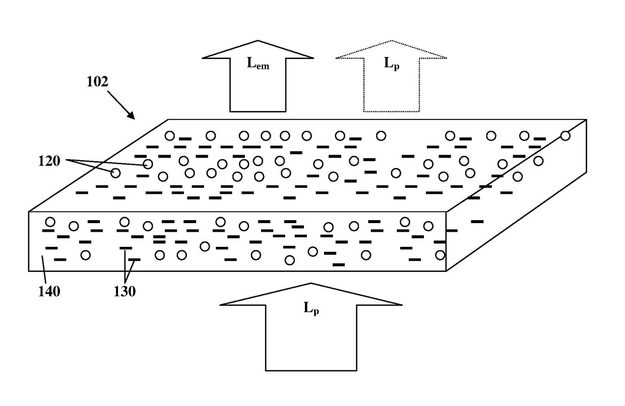
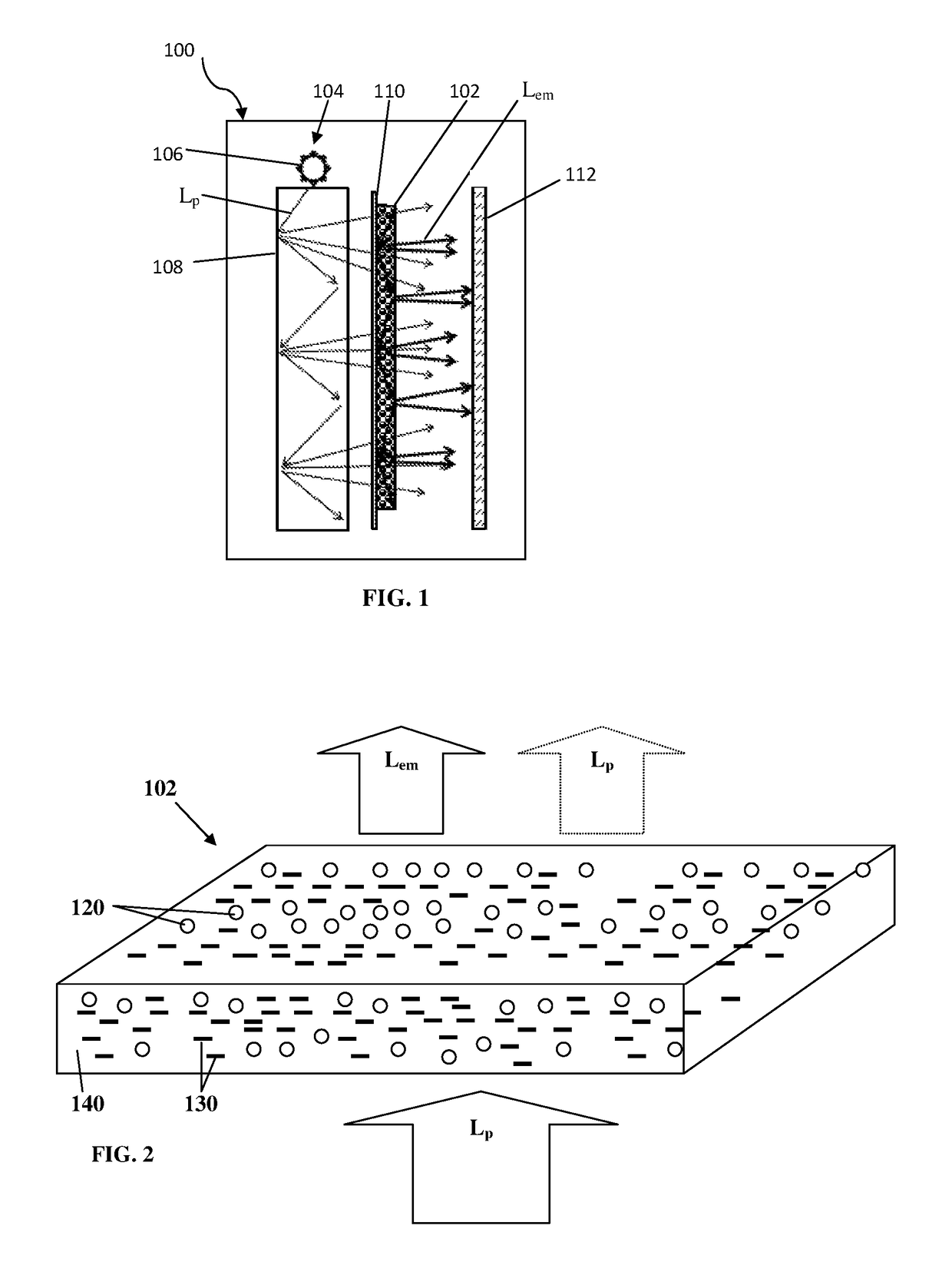
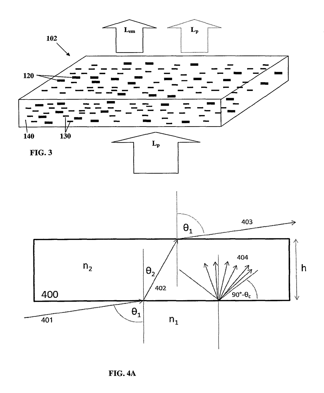
[0026]Further, it should be noted that cost reduction, lower power consumption and improved viewing experience for users are important considerations in the design of LCDs. The polarized light source of the present invention based on polarized emission backlighting, provides for lower power consumption and / or brighter screens. To this end, efficient light emission provided by arrays of aligned nanostructures is accompanied with efficient light extraction from the emitting layer, while maintaining polarization in order to minimize losses. The polarized emission originates from the polarized light source, which includes aligned arrays of anisotropic nanostructures, and in particular colloidal semiconductor nanorods.
[0031]The polarized light source of the present invention containing such optically active medium with aligned nanorods is generally suitable to be incorporated into the backlight unit of any type of LCD devices. Such LCD device may include a bottom polarizer, located between the backlight unit and an LC layer / structure. In this case the polarized light source is placed in the backlight unit in a manner allowing increased transmittance of polarized emitted light through the bottom polarizer. This can be achieved by fixing the orientation of the “polarization axis” to be substantially parallel to the transmittance axis of the polarizer so that significantly higher fraction of the polarized light emitted from the light source is transmitted through the polarizer, as compared with the typical non-polarized backlight unit configuration.
[0035]In some embodiments, an additional diffusive layer may be used, located in optical path of light emitted from the optically active structure. The diffusive layer may be used for providing uniform illumination and compensate for variation of nanorods density and / or intensity distribution of the pumping light. The diffusive layer is preferably configured with haze factor in the range of 50% to 95%. Additionally or alternatively, the diffusive layer may be attached to the surface of the optically active structure. In these configuration the diffusive layer is configured to increase uniformity of pumping light, when back pumping is used, and / or to increase light extraction efficiency by varying directionality of light emitted from within the layer.
[0052]According to some embodiments, the present invention provides a polarized light source as indicated above; wherein said at least one optically active structure and said light directing assembly defining together an optical stack arrangement comprising at least two layers oriented such that principal axes of birefringence of said at least two layers are parallel to one another. The optical stack thereby substantially preserving predetermined polarization properties of light emitted from the optically active structure and passing through said optical stack.
[0054]According to one other broad aspect of the invention, there is provided an optical stack arrangement, suitable for use in an illumination device. The optical stack arrangement comprises one or more layers oriented such that principal axes of birefringence of said one or more layers are parallel to each other; said optical stack thereby substantially preserving predetermined polarization properties of light passing therethrough. The optical stack may further comprise at least one diffusive layer configured for increasing uniformity of light passing therethrough.

Problems solved by technology

Thus, selection of a particular polarization comes at the cost of energy loss: exemplarily, more than 50% of light emitted by the light source may be lost due to the light passage through the polarizer.
This problem is significant for LCD displays, where energy saving is a crucial factor.
The problem is further intensified in portable devices (laptops, cell-phones, tablets, etc.) where battery life and increased backlight brightness are important factors.

Method used


Image

  • Polarized light source device
  • Polarized light source device
  • Polarized light source device

Examples


example 1

[0129]In order to construct a backlight unit, aligned nanorods film was placed on the surface of a lightguide plate (slab) coupled to a pumping light source in the form of a blue emitting LED bar (central wavelength 450 nm FWHM=20 nm, edge-lit). A highly reflective sheet based on Silver layer coating was placed in the back surface of the lightguide in order to recycle the light emitted backwards.

[0130]The polarized light output from the nanorods layer was directed to pass through a polarization maintaining diffuser (in this non-limiting example LSD™ holographic diffuser, circular 30 degrees, available from Luminit was used) to improve brightness uniformity.

[0131]As a light redirecting film, a Reflexite collimating film (RCF™) commercially available from Orafol Europe GmbH was used. A specific batch had the desired birefringence alignment axes that are along the facet of the light redirecting films' prism. This film was placed parallel to the nanorods alignment axis or in a perpendic...

example 2

[0133]In order to construct a backlight unit, the aligned nanorods film was placed on the surface of a lightguide plate (slab) coupled to a blue emitting LED bar (central wavelength 450 nm FWHM=20 nm, edge-lit). A highly reflective sheet based on Silver layer coating (“BL film”, commercially available from Oike) was placed in the back surface of the lightguide in order to recycle the light emitted backwards.

[0134]As a light redirecting film, a prism film with 160 um pitch and prisms with angle 90 degrees was used. A specific film with a non-birefringent polymethyl-methacrylate (PMMA) substrate was chosen (250 micron substrate with retardation below 25 nm). This film was placed parallel to the nanorods alignment axis or in a perpendicular alignment. In both alignments, the polarization ratio received was 2. The LROE film provided an increase of 60-80% for the green and red light compared to 10-40% increase obtained using prism films which are based on birefringent polymer substrates....


PUM

PropertyMeasurementUnit
hazeaaaaaaaaaa
hazeaaaaaaaaaa
hazeaaaaaaaaaa

Abstract

A polarized light source configured for use in display device and backlight unit is described. The polarized light source comprising: at least one optically active structure comprising a plurality of nanorods configured to emit light of one or more wavelengths in response to exciting pumping field, said plurality of nanorods comprising nanorods aligned with a predetermined alignment axis so as to produce a desired polarization direction of the emitted light; and a light directing assembly comprising one or more optical elements in optical path of light emitted from the light emitting structure, said light directing assembly being configured to enhance output of the emitted light from the emitting structure while substantially maintaining the polarization of the emitted light passing therethrough. Preferably, layers associated with the polarized light source are aligned with parallel principal axes.

Description

TECHNOLOGICAL FIELD[0001]This invention is generally in the field of light sources, and relates to a polarized light source device, particularly useful as a backlight unit in a display device.BACKGROUND ART[0002]References considered to be relevant as background to the presently disclosed subject matter are listed below:[0003]1. US 2011 / 0299001[0004]2. WO2012 / 059931[0005]3. US 2013 / 0026506[0006]4. U.S. Pat. No. 8,471,969[0007]5. US 2012 / 0113672[0008]6. WO2012 / 021643[0009]7. WO2010 / 0155749[0010]8. U.S. Pat. No. 5,825,543,[0011]9. WO 2008 / 027936[0012]10. U.S. Pat. No. 7,278,775,[0013]11. U.S. Pat. No. 8,033,674[0014]12. “A polarized laser backlight using a zero-zero-birefringence polymer for liquid crystal displays”, Takahiro Kurashima, Koichi Sakuma, Takayuki Arai, Akihiro Tagaya, Yasuhiro Koike, Optical Review, Volume 19, Issue 6, pp. 415-418 (2012)[0015]13. U.S. Pat. No. 6,746,130[0016]14. US 2008 / 0285255[0017]15. U.S. Pat. No. 6,111,696[0018]16. “Novel wide viewing liquid crystal ...

Claims


Application Information

Patent Timeline
Patent Type & Authority Patents(United States)
IPC IPC(8): F21V9/14G02F1/13363G02B5/02G02F1/1335G02F1/1333G02B5/30
CPCG02F1/13362G02B5/0242G02B5/0257G02B5/3008G02F1/133308G02F1/133606G02F1/133617G02F1/13363G02F2202/36G02B5/3075G02F1/133607G02F1/133614
Inventor BANIN, URISHAVIV, EHUDARBELL, HAGAI
Owner YISSUM RES DEV CO OF THE HEBREWUNIVERSITY OF JERUSALEM LTD
Why Eureka
Eureka Blog
Learn More