
Brush conveyor for transporting preforms

a conveyor and brush technology, applied in the field of brushes, can solve the problems of not being able to feed the heating unit, frequent cleaning, and rapid wear of leather, and achieve the effect of greater resistance to heat build-up and greater resistance to wear

Active Publication Date: 2018-07-31
SIDEL PARTICIPATIONS SAS
View PDF12 Cites 0 Cited by
  • Summary
  • Abstract
  • Description
  • Claims
  • Application Information

AI Technical Summary

Benefits of technology

The invention proposes a method for transporting preforms that results in less wear and tear on the brushes used for carrying the material. The brushes are designed to rub the material from the end, which creates minimal dust and pollution while maintaining the brush's performance even when using materials that are resistant to rubbing, such as Nylon.

Problems solved by technology

In particular, the bulk packing of the preforms in the hopper or the bowl does not make it possible to feed the heating unit directly at its discharge.
The rubbing against the preforms, however, causes, firstly, a rapid wear of the leather, which necessitates the frequent replacement of the belt.
Secondly, the rubbing produces a dust made of fine particles of leather that has a tendency to be deposited on the preforms and on the elements of the conveyor.
Since the leather is a natural material, the resulting pollution is not hazardous, but it is not acceptable to allow the dust to accumulate on the conveyor, which consequently must undergo frequent cleanings.

Method used


Image

  • Brush conveyor for transporting preforms
  • Brush conveyor for transporting preforms
  • Brush conveyor for transporting preforms

Examples


first embodiment

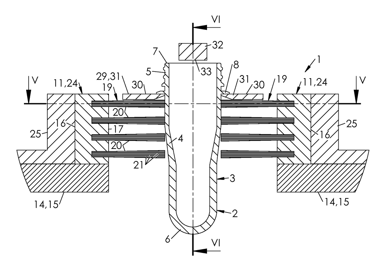
[0051] illustrated in FIGS. 4 and 6, the preforms 2, provided with a collar 8, are oriented neck up. The support 29 appears in the form of a pair of rails 31 that are spaced apart from each other. The rails 31 together define at least one portion of the path T of the preforms 2. The rails 31 have coplanar upper bearing surfaces 30, making possible the hanging, by their collars 8, of the preforms 2 oriented neck up. The spacing between the rails 31 is slightly greater than the under-neck diameter of the preforms 2. The play between the rails 31 and the body 4 of the preforms 2 is sufficient to make possible the sliding of the preforms 2 without jamming, all while being small enough to prevent the passage of the collar 8 and the fall of the preforms 2.

[0052]In this embodiment, at least one portion of the brushes 19 (all of the brushes 19 in the example illustrated in FIG. 4) extends under the rails 31 to come into contact with the body 4 of the preforms 2.

[0053]Another portion of the ...

second embodiment

[0056]In this second embodiment, the conveyor 1 can comprise a bottom guide 34 that extends perpendicularly to the plate 29, at a distance from it that is greater than or equal to an overall height of the preforms 2. This guide 34 limits the risk of the tipping forward of the preforms 2 under the action of the rubbing forces caused by the brushes 2. This guide 34 can be movable to accompany the preforms along their path and thus again to limit the risk of tipping. In this case, the guide 34 can appear in the form of an endless circulating band mounted between two pulleys.

[0057]To prevent in addition any lateral tipping of the preforms 2, guide rails 35 can be provided, positioned on both sides of the body 4 and / or neck 5.

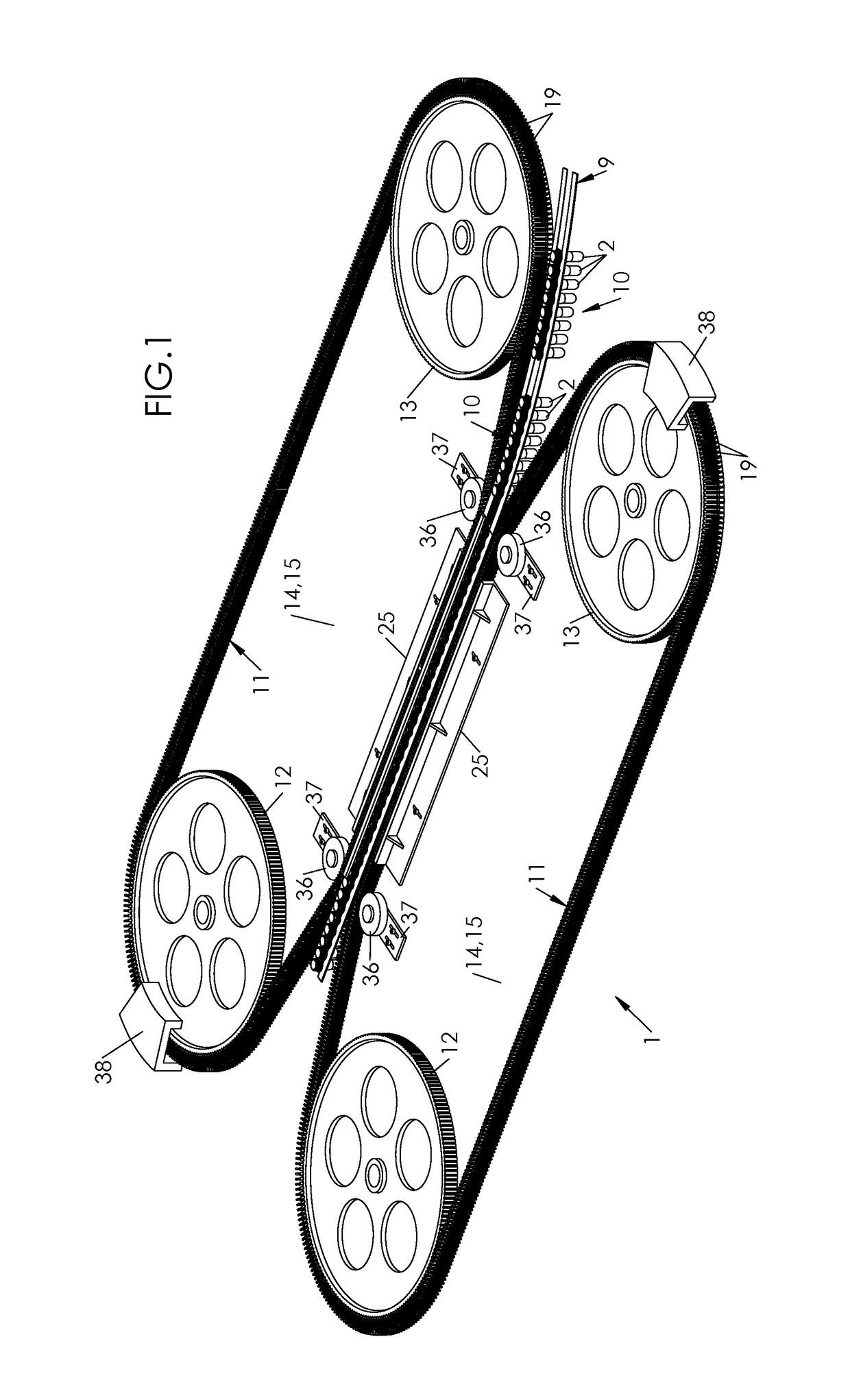
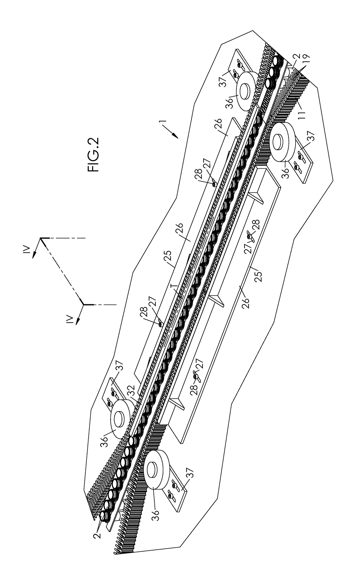
[0058]As is seen particularly in FIG. 1, the (or each) belt 11 can comprise brushes 19 over its entire length. The placement of the brushes 19 can be vertical or, as a variant, angled (i.e., the different tufts can be placed staggered). Further, the conveyor 1 can b...


PUM


Abstract

Disclosed is a device for transporting plastic-container preforms, the device including an endless circulating element having an outer surface and being capable of moving the preforms along a path by rubbing against the preforms, the device including a stationary mounting defining a planar bearing surface for the preforms, the circulating element having a series of brushes which extend projecting from the outer surface, capable of engaging with the preforms in order to move same by rubbing.

Description

[0001]The invention relates to transporting articles, and more particularly to transporting preforms of containers made of plastic material such as PET.BACKGROUND OF THE INVENTION[0002]A preform generally comprises a tubular body that is closed, at a lower end, by a hemispherical bottom, and a neck, normally threaded, which extends the body from an upper end of the former. Most preforms are also provided with a collar that separates the neck from the body and that facilitates the handling of the preforms.[0003]A cycle for manufacturing a container requires numerous operations for handling the preform from which the container is intended to be manufactured. From a bulk packing in a hopper (or a bowl, or any other bin), the preform is successively removed from the hopper, oriented (neck up or neck down), transferred to a heating unit (or oven), transported into it in a procession to undergo a thermal conditioning there, and then again transferred to a mold to be transformed there into...

Claims


Application Information

Patent Timeline
IPC IPC(8): B65G15/14B65G15/60B65G51/03B65G15/10B65G15/26B65G19/02
CPCB65G15/14B65G15/105B65G15/60B65G51/035B65G2207/42B65G15/26B65G19/025B65G2201/00
Inventor FEVRE, SEBASTIENDE LIMA, RUITURLOTTE, DENISWILLIG, FREDERIC
Owner SIDEL PARTICIPATIONS SAS
Learn More