Capacitor element
a technology of capacitor elements and dielectric layers, applied in capacitor electrodes, capacitor dielectric layers, electrolytic capacitors, etc., can solve the problems of many defects, current may flow, and the dielectric layer is not sufficiently dense film with a suitable thickness, etc., to achieve less leakage current, high capacitance, and high frequency range
- Summary
- Abstract
- Description
- Claims
- Application Information
AI Technical Summary
Benefits of technology
Problems solved by technology
Method used
Image
Examples
example 1
Production of Sintered Compact
[0047]A tungsten powder having a 50% particle size (D50) of 0.56 μm was mixed with 0.5% by mass of silicon powder having a 50% particle size (D50) of 1 μm, and the mixture was then allowed to stand for 30 minutes at 1,450° C. under vacuum. The mixture was returned to room temperature, and the block object was crushed by a hammer mill, thereby producing a granulated powder having a 50% particle size (D50) of 110 μm (range of particle size distribution: 26 μm-146 μm). Part of silicon was reacted with tungsten, and an alloy of tungsten silicide was present in the tungsten surface layer.
[0048]Compression bodies were produced from the granulated powder. When forming, tungsten wires (lead wires) having a diameter Φ of 0.29 mm were implanted. The compression bodies were put in a vacuum firing furnace, and fired at 1,500° C. for 20 minutes, thereby producing 10,000 sintered compacts with a size of 1.0 mm×1.5 mm×4.5 mm (each lead wire was implanted in the 1.0 mm...
examples 25 and 26
, and Comparative Examples 23 and 24
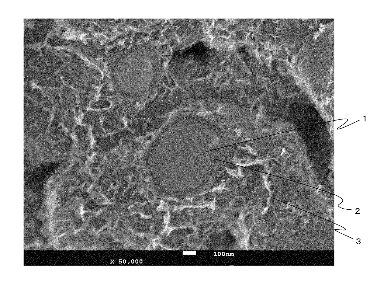
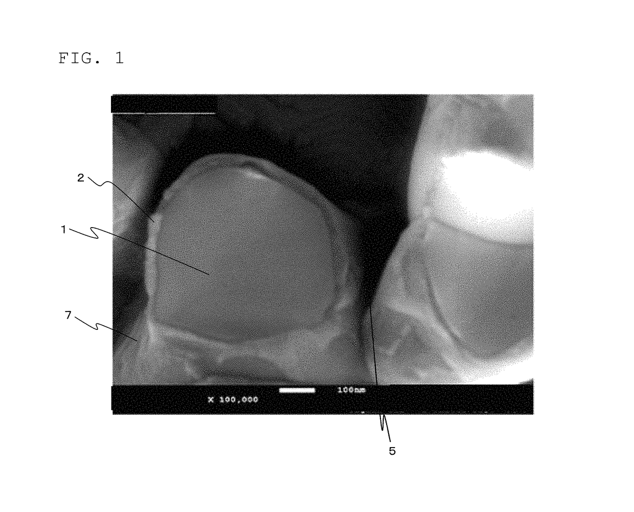
[0069]Solid electrolytic capacitor elements were obtained in the same manner as in Examples 11 and 12, and Comparative Examples 6 and 7, except that the chemical conversion liquid used in the second chemical conversion treatment was changed to aqueous solutions of the recipes shown in Table 2. The surface of the dielectric layers produced in Examples 25 and 26 was smooth, without sharp projections, salient striae, or cracks. The 120-Hz capacitance, 10-kHz capacitance, and leakage current of these elements were measured, and their average values were calculated. Table 2 shows the results.
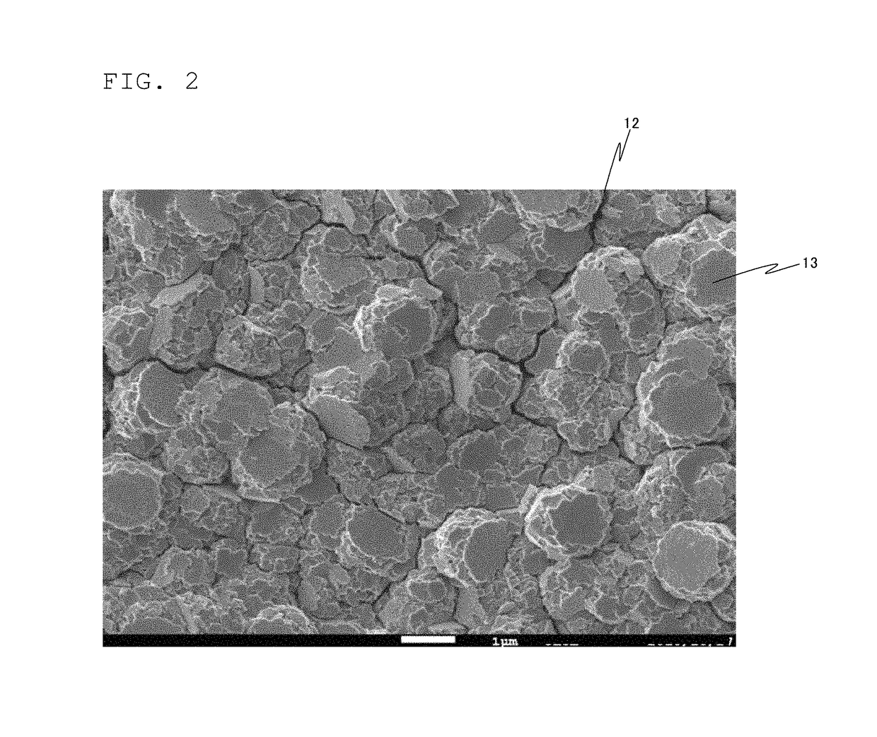
[0070]The surface of the dielectric layers produced in Comparative Examples 23 and 24 had pleat-like projections, as shown ink FIG. 3. The 120-Hz capacitance, 10-kHz capacitance, and leakage current of these elements were measured, and their average values were calculated. Table 2 shows the results.
examples 29 to 31
[0075]Chemical conversion treatment was performed in the same manner as in Examples 3, 11, and 19, except that drying was performed without removing water with ethanol, while water remained in the pores, etc. Most of the obtained dielectric layers had a bluish-black smooth surface; however, 31 to 67 dielectric layers of the 128 dielectric layers were deteriorated, and the color of their outer surface was grayish-black. When the leakage current of the sintered compact having a grayish dielectric layer was measured in a 30% by mass sulfuric acid aqueous solution under conditions of room temperature, 2.5 V, and 30 seconds using the lead wire as positive electrode, and a platinum black plate placed in the liquid as negative electrode, the leakage current exceeded 100 μA.
[0076]When the leakage current of the sintered compact having a bluish dielectric layer was measured in a 30% by mass sulfuric acid aqueous solution under conditions of room temperature, 2.5 V, and 30 seconds using the l...
PUM
| Property | Measurement | Unit |
|---|---|---|
| temperature | aaaaa | aaaaa |
| temperature | aaaaa | aaaaa |
| temperature | aaaaa | aaaaa |
Abstract
Description
Claims
Application Information
 - R&D
- Intellectual Property
- Life Sciences
- Materials
- Tech Scout
- Unparalleled Data Quality
- Higher Quality Content
- 60% Fewer Hallucinations
Browse by: Latest US Patents, China's latest patents, Technical Efficacy Thesaurus, Application Domain, Technology Topic, Popular Technical Reports.
© 2025 PatSnap. All rights reserved.Legal|Privacy policy|Modern Slavery Act Transparency Statement|Sitemap|About US| Contact US: help@patsnap.com


