Overhead camshaft engine

a camshaft engine and camshaft technology, applied in the direction of valve drives, machines/engines, gearing details, etc., can solve the problems of unfavorable camshaft assembling, unfavorable camshaft assembling, and unfavorable camshaft assembling

Active Publication Date: 2018-07-24
HONDA MOTOR CO LTD
View PDF4 Cites 0 Cited by
  • Summary
  • Abstract
  • Description
  • Claims
  • Application Information

AI Technical Summary

Benefits of technology

[0006]In view of such problems of the prior art, a primary object of the present invention is to provide an overhead camshaft engine which can be constructed as a compact unit.
[0007]A second object of the present invention is to provide an overhead camshaft engine which is easy to assemble.
[0008]A third object of the present invention is to minimize the mass of the moving parts in an overhead camshaft engine.
[0010]The reduced diameter portion is required only to bear the load required for driving the timing belt, and, hence, can be significantly reduced in diameter as compared to the adjoining part of the crankshaft. Therefore, the diameter of the crankshaft pulley can be reduced, and the diameter of the camshaft pulley can be reduced in a corresponding manner. Therefore, the overall size, in particular the height of the engine can be minimized, and the mass of the crankshaft pulley and the camshaft pulley can be minimized. Also, the positioning of the crankshaft pulley on the outer side of the second bearing facilitates the assembling and servicing of the engine.
[0012]According to this arrangement, the crankshaft pulley is in a highly accessible position so that the assembling and servicing process for the engine can be particularly simplified. If the crankcase is attached to the lower end of the cylinder block at a parting plane (31) that extends obliquely across the crankshaft, the accessibility of the crankshaft pulley and the second bearing can be particularly enhanced.
[0014]According to a particularly preferred embodiment of the present invention, the engine main body includes a belt cover (17) extending from the engine main body such that an air space (Sp1) communicating with outside is defined between an upper part of the cylinder block and the belt cover. This arrangement is made possible by the favorable positioning of the crankshaft pulley, and the air space is beneficial in properly cooling the cylinder block, and hence the engine. If desired, the belt cover may be integrally formed with the cylinder block, typically by metal casting. Also, a cylinder head (14) may be integrally formed with the cylinder block for the simplification of the assembling process.

Problems solved by technology

As a result, the mass of the crankshaft pulley and the camshaft pulley is undesirably great, and the overall height of the engine is undesirably great.
Also, the assembling of the engine is undesirably complex.

Method used


Image

  • Overhead camshaft engine
  • Overhead camshaft engine
  • Overhead camshaft engine

Examples


Embodiment Construction

preferred embodiment of the present invention is described in the following with reference to FIGS. 1 to 6.

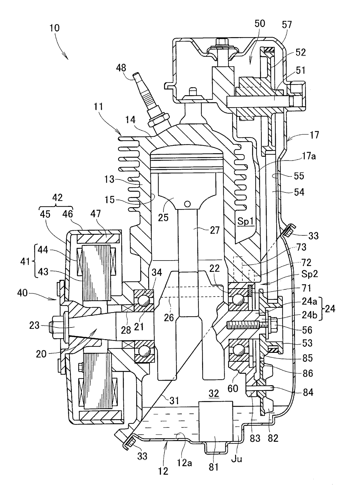
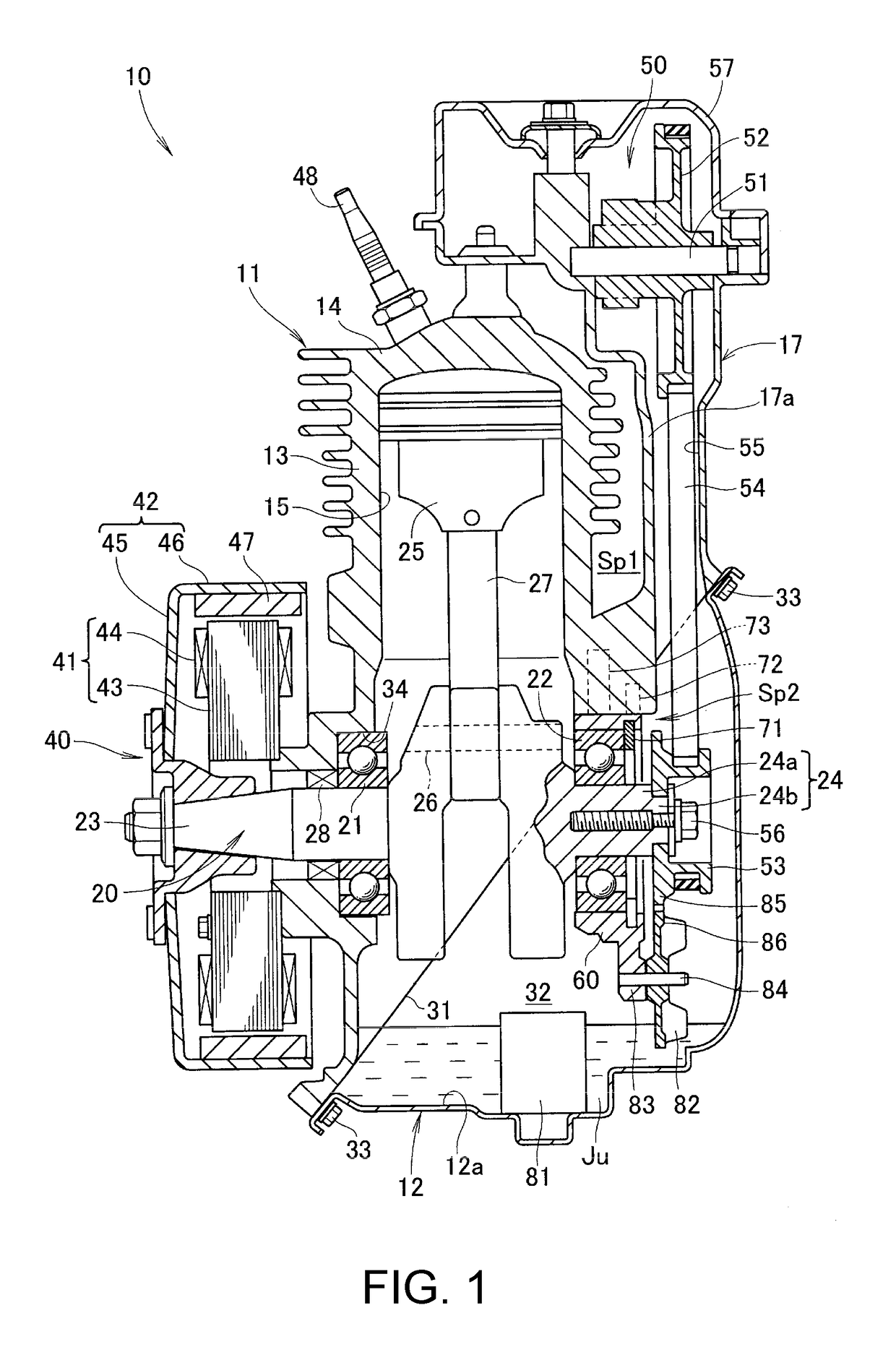
[0025]Referring to FIG. 1, the engine 10 of the illustrated embodiment includes a cylinder block 11 which integrally combines a cylinder head part 14 and a cylinder block part 13 which are formed as separate component parts in a more conventional arrangement, and internally defines a cylinder 15 therein. This engine 10 consists of a single cylinder, air cooled engine, and is provided with air cooling fins 16 on an outer periphery of the cylinder block part 13.

[0026]The cylinder block 11 further includes a belt cover part 17 extending sideways (rightward in FIG. 1) and upward in the shape of letter L when seen from sideways, and internally defines a belt chamber 55. The upper end of the belt chamber 55 is closed by a head cover 57 attached to an upper end of the belt cover part 17 to define a cam actuating mechanism chamber 50. A camshaft pulley 52 is rotatably supported in the ...


PUM


Abstract

In an overhead cam engine (10) having a first bearing (21) supported by the cylinder block (11), and a second bearing (22) supported by a bearing retaining member (60) attached to the cylinder block inside a crankcase chamber (12) for rotatably supporting a crankshaft (20), the crankshaft is provided with a reduced diameter portion (24b) having a smaller outer diameter than an adjoining part of the crankshaft on a side of the second bearing facing away from a cylinder (15) defined in the cylinder block, and a crankshaft pulley (53) is mounted on the reduced diameter portion.

Description

TECHNICAL FIELD[0001]The present invention relates to an improved overhead camshaft engine.BACKGROUND ART[0002]There is a desire to form an engine main body defining a cylinder and a crankcase chamber by using as small a number of component parts as possible, and support the crankshaft of the engine in a favorable manner in terms of structural integrity and ease of assembly. In a known overhead camshaft engine disclosed in JP2002-349340A, the engine main body includes a cylinder block that is integrally formed with a cylinder head, and a first bearing for supporting a first end of the crankshaft is fitted into a hole formed in the cylinder block. The lower end of the cylinder block is defined by a plane extending obliquely across the crankshaft, and a crankcase having a corresponding upper end is attached to the lower end of the cylinder block to define the crankcase chamber in cooperation with the cylinder block. The crankcase is formed with a hole, and a second bearing for support...

Claims


Application Information

Patent Timeline
Patent Type & Authority Patents(United States)
IPC IPC(8): F01L1/02F16H57/035F01L1/053F02F7/00F01P1/02F02B75/16F02F1/00F01L1/047F16C3/06F16C9/02
CPCF01L1/053F01L1/024F01P1/02F02B75/16F02F1/002F16H57/035F02F7/0053F16C2360/22F01L2001/0476F16C3/06F16C9/02F16C2240/70F02B67/06F02F7/0043F02F7/0073F02F2007/0078
Inventor KONO, SHOHEI
Owner HONDA MOTOR CO LTD
Why Eureka
Try Eureka