
Deflector device for a sunroof device

a technology of sunroof and deflector, which is applied in the direction of roofs, mechanical devices, transportation and packaging, etc., can solve the problems of difficult spring configuration, excessive air entering the passenger compartment, and wind nois

Active Publication Date: 2012-10-23
YACHIYO IND CO LTD
View PDF7 Cites 4 Cited by
  • Summary
  • Abstract
  • Description
  • Claims
  • Application Information

AI Technical Summary

Benefits of technology

The solution provides a consistent spring force to maintain the blade in the deployed position while avoiding excessive force when retracted, ensuring stability and aerodynamic performance while keeping the device compact and visually appealing.

Problems solved by technology

When a vehicle fitted with a sunroof device travels at a high speed while keeping the sunroof device open, wind noises may be created and / or an excessive amount of air may be introduced into the passenger compartment.
At any event, when each arm member is required to be raised by a relatively large angle, it is difficult to configure the spring so as to produce an appropriate force under all conditions.
If the spring is selected so as to produce an adequate force when the blade is deployed so as to maintain the blade in a stable condition even when the vehicle is traveling at high speed, the spring force may be excessive when each arm member is placed horizontally to retract the blade.
If the spring force acting on each arm member is controlled so as to be appropriate in the retracted state of the blade, the spring force may not be adequate in the fully deployed condition of the blade to firmly hold the blade under all conditions.
Also, as the spring has to be relatively large in size so as to produce the required spring force under all conditions, the spring may not be appropriately concealed from the vehicle occupant, and this may impair the external appearance of the deflector device.

Method used


Image

  • Deflector device for a sunroof device
  • Deflector device for a sunroof device
  • Deflector device for a sunroof device

Examples


Embodiment Construction

)

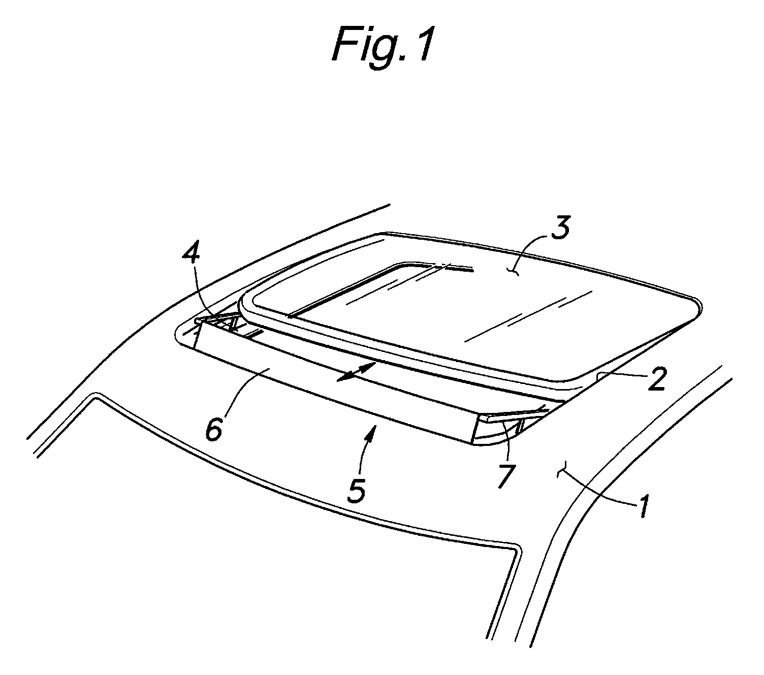
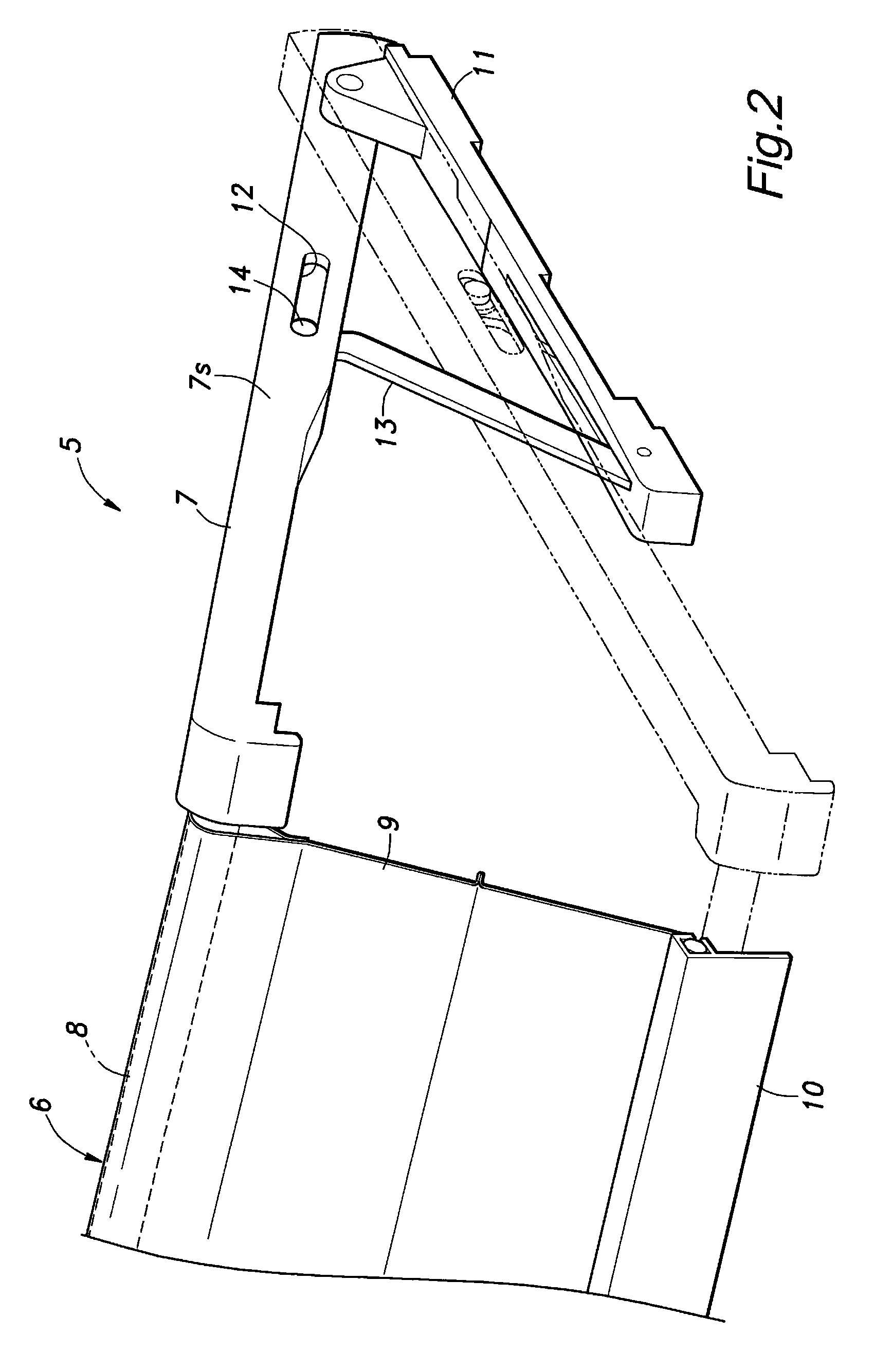
[0023]A deflector device 5 for a sunroof device according to the present invention is described in the following with reference to FIGS. 1 to 3. As the deflector device 5 is essentially symmetric about a central longitudinal line of the vehicle body, only one half of the structure is described in part of the description to avoid redundancy in the description.

[0024]Referring to FIG. 1, a rectangular opening 2 is formed centrally in a front part of a fixed roof 1 of the vehicle body, and a slide panel 3 which may consist of a glass panel and is given with a peripheral profile corresponding to the shape of the roof opening 2 is supported by the fixed roof 1 so as to be slidable in the fore and aft direction, and thereby selectively open and close the roof opening 2 in a per se known manner.

[0025]More specifically, a pair of guide rails 4 are provided on the fixed roof 2 so as to extend along either side edge of the opening 2 and slidably guide the slide panel 3. Also, an arrangement m...


PUM


Abstract

In a deflector device for a sunroof device, a pair of arm members (7) extend in a fore and aft direction, and are each pivotally supported by a fixed roof panel part at a rear end thereof, and a blade (6) extends laterally between front ends of the arm members. A link member (13, 13′) is pivotally connected to a fixed roof part at a base end thereof, and engaged by an intermediate part of each arm member at a free end thereof so that the free end may be moveable along a lengthwise direction, and a coil spring (15, 15′, 16, 16′) is connected between the free end of the link member and a part of the arm member so as to urge the arm member in an upward direction. Thereby, the blade can be supported in the deployed or raised position with an adequate spring force.

Description

TECHNICAL FIELD[0001]The present invention relates to a deflector device for a vehicle sunroof device, and in particular to a deflector device that is suited for using a relatively large blade for deflecting airflow.BACKGROUND OF THE INVENTION[0002]The vehicle sunroof device is well known. Typically, a slide panel made of sheet glass or sheet metal is slidably provided on the roof of the vehicle to selectively close and expose an opening formed in the roof. When a vehicle fitted with a sunroof device travels at a high speed while keeping the sunroof device open, wind noises may be created and / or an excessive amount of air may be introduced into the passenger compartment. In order to control the wind noises and / or the airflow created by the sunroof device, a deflector device is often provided in a front part of the opening in the roof. Typically, the blade of the deflector device is resiliently supported by a spring such that the blade is retracted against the spring force of the spr...

Claims


Application Information

Patent Timeline
Patent Type & Authority Patents(United States)
IPC IPC(8): B60J7/22
CPCB60J7/22B60J7/226
Inventor UEHARA, TATSUAKI
Owner YACHIYO IND CO LTD
Learn More