Method and system for determining in-plane distortions in a substrate

a technology of in-plane distortion and substrate, which is applied in the direction of force measurement by measuring optical property variation, semiconductor/solid-state device testing/measurement, instruments, etc., can solve the problems of significant distortion, error in downstream applications, and elastic deformation of the wafer

Active Publication Date: 2018-07-17
KLA TENCOR TECH CORP
View PDF22 Cites 3 Cited by
  • Summary
  • Abstract
  • Description
  • Claims
  • Application Information

AI Technical Summary

Benefits of technology

The present invention is believed to be understood by the description provided, and it is expected that changes can be made to the components without affecting the main benefits of the invention. The described form of the invention is just one example, and the patent aims to protect any changes made to it through the claims.

Problems solved by technology

However, the various process steps applied to a wafer required during device fabrication as well as thickness variations may result in elastic deformation of the wafer.
These elastic deformations may cause significant distortions.
Distortions may lead to errors in downstream applications such as overlay errors in lithographic patterning or the like.

Method used


Image

  • Method and system for determining in-plane distortions in a substrate
  • Method and system for determining in-plane distortions in a substrate
  • Method and system for determining in-plane distortions in a substrate

Examples


Embodiment Construction

[0016]Reference will now be made in detail to the subject matter disclosed, which is illustrated in the accompanying drawings.

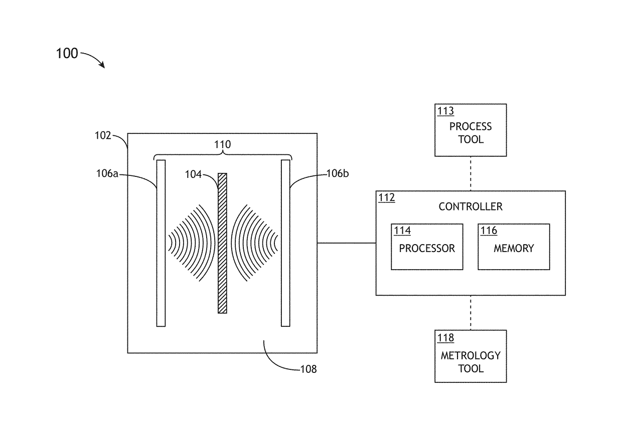
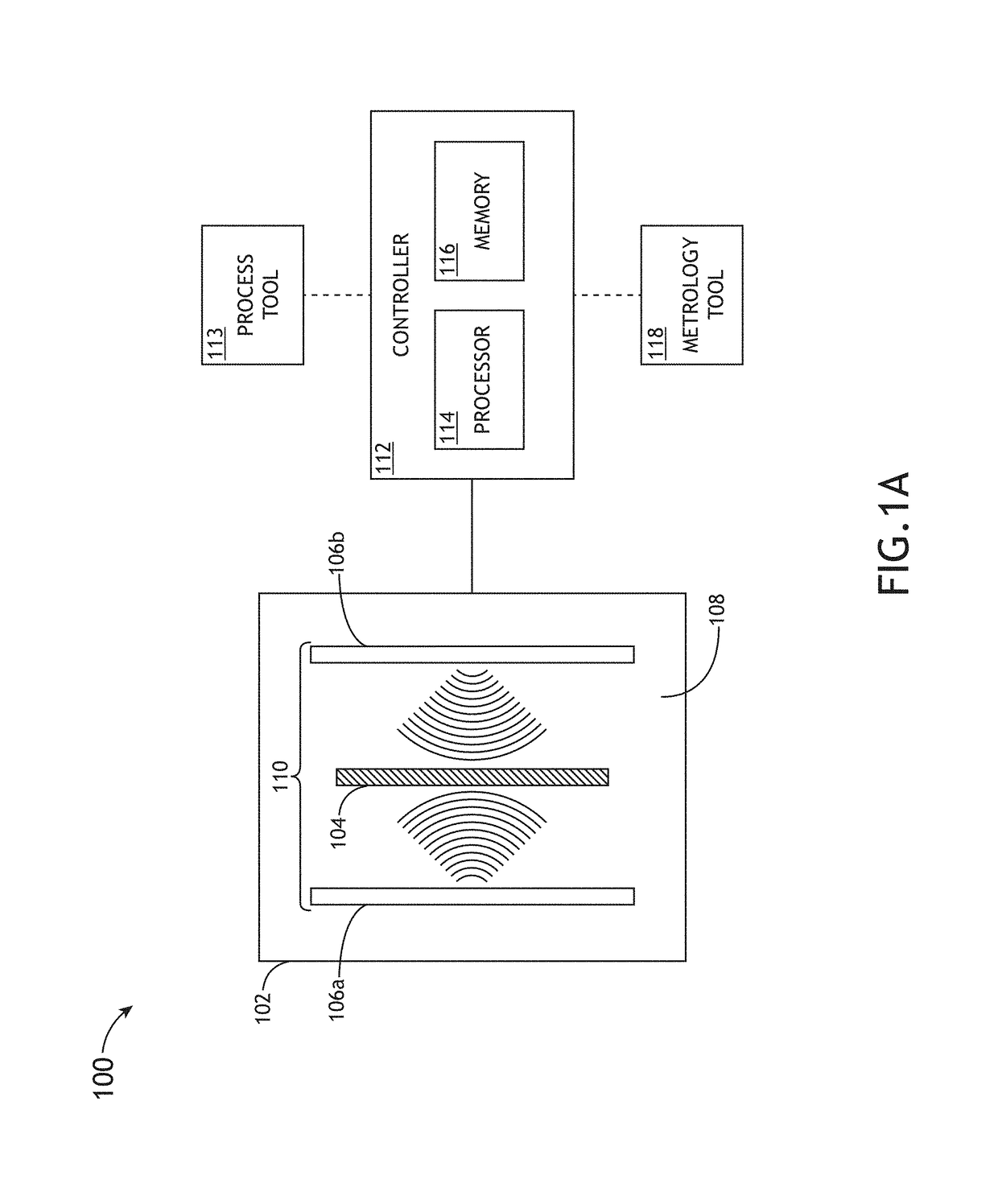
[0017]Referring generally to FIGS. 1A through 3, a method and system for determining in-plane distortions in a substrate are described in accordance with the present disclosure.

[0018]Embodiments of the present disclosure are directed to systems and methods for determining in-plane distortions of a chucked substrate based on the measured out-of-plane distortions of an unchecked substrate (i.e., free standing substrate). Embodiments of the present disclosure utilize linear elastic solid body deformation mechanics of thin objects (e.g., two-dimension plate theory) to derive a model that allows for the prediction of in-plane distortion of a chucked wafer from measured out-of-plane distortions of an unchucked substrate.

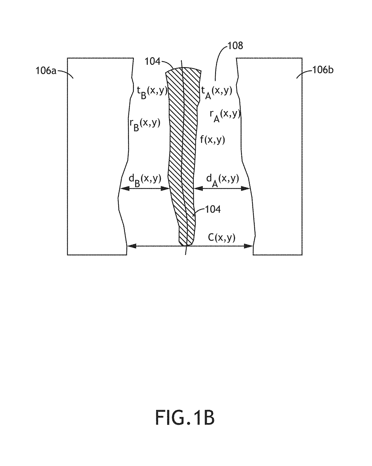
[0019]Wafer shape change resulting from wafer processing and / or wafer chucking may induce in-plane distortions (IPD) within the wafer, which may le...


PUM


Abstract

The determination of in-plane distortions of a substrate includes measuring one or more out-of-plane distortions of the substrate in an unchucked state, determining an effective film stress of a film on the substrate in the unchucked state based on the measured out-of-plane distortions of the substrate in the unchucked state, determining in-plane distortions of the substrate in a chucked state based on the effective film stress of the film on the substrate in the unchucked state and adjusting at least one of a process tool or an overlay tool based on at least one of the measured out-of-plane distortions or the determined in-plane distortions.

Description

CROSS-REFERENCE TO RELATED APPLICATION[0001]The present application claims benefit under 35 U.S.C. § 119(e) and constitutes a regular (non-provisional) patent application of U.S. Provisional Application Ser. No. 62 / 143,708, filed Apr. 6, 2015, entitled SIMPLIFIED MODEL FOR PROCESS-INDUCED DISTORTION PREDICTION, which is incorporated herein by reference in the entirety.TECHNICAL FIELD[0002]The present invention generally relates to the prediction of in-plane distortion of a chucked substrate, and, in particular, the prediction of in-plane distortion of a chucked substrate base on measurements of out-of-plane distortions of the substrate in an unchucked stated.BACKGROUND[0003]Fabricating semiconductor devices such as logic and memory devices typically includes processing a substrate such as a semiconductor wafer using a large number of semiconductor fabrication processes to form various features and multiple levels of the semiconductor devices. For example, lithography is a semiconduc...

Claims


Application Information

Patent Timeline
IPC IPC(8): G01B9/02G01B11/02G01L1/24G01B11/16G01B11/24H01L21/66
CPCG01B11/161G01B9/02021G01B11/2441G01B9/02027H01L22/12G01B2210/56
Inventor SMITH, MARK D.SOLOMON, JOSESHERWIN, STUARTMIEHER, WALTERLEVY, ADY
Owner KLA TENCOR TECH CORP
Why Eureka
Try Eureka