
Exhaust gas purifying catalyst

a technology of exhaust gas and purifying catalyst, which is applied in the direction of metal/metal-oxide/metal-hydroxide catalyst, physical/chemical process catalyst, separation process, etc., can solve the problems of exhaust gas purification catalyst, inability of catalyst to exert sufficient performance, and limit the use of ceria-zirconia composite oxide as precious metal carrier, so as to improve the heat resistance and reactivity of precious metal, reduce the use of osc material, and enhance the purification performan

Active Publication Date: 2018-07-17
HONDA MOTOR CO LTD +1
View PDF31 Cites 11 Cited by
  • Summary
  • Abstract
  • Description
  • Claims
  • Application Information

AI Technical Summary

Benefits of technology

[0045]By adjusting a mass ratio of the OSC material and the alumina respectively according to the role of each layer in the first catalyst layer and the second catalyst layer, the exhaust gas purifying catalyst which the present invention firstly proposes can reduce usage of the OSC material and yet can have necessary OSC, and can maintain or improve heat resistance and reactivity of a precious metal, in particular, can enhance NOx purification performance.
[0046]Further, by adjusting a particle size of the alumina and the OSC material which are the main material in each of the first catalyst layer and the second catalyst layer, the exhaust gas purifying catalyst which the present invention secondly proposes can prevent to clog pores, which a catalyst constitutional material has, even in repeated use, and further can diffuse exhaust gas to the deep part of the catalyst layer. As the result, since the burying into the pores of the precious metal component supported on those can be prevented and further the gas diffusibility in the catalyst layer can be improved, the catalytic activity is rarely reduced and the entire catalyst layer can be effectively utilized even in an internal-combustion engine which is used under an exhaust gas atmosphere where it is exposed to high temperature exhaust gas, and is a high space velocity to pass the catalyst. Thus, in particular, it is extremely suitable as an exhaust gas purifying three way catalyst for the saddle-riding-type vehicle.

Problems solved by technology

However, it is not possible for the catalyst to sufficiently exert performance as a purifying catalyst only by controlling the air-fuel ratio (A / F) as described above, and thus the catalyst layer itself is also required to have an action of controlling the air-fuel ratio (A / F).
However, since the ceria-zirconia is a rare earth and expensive, in order to provide an inexpensive catalyst, there has been a limit to use the ceria-zirconia composite oxide as the carrier of the precious metal.
Incidentally, an exhaust gas purifying catalyst for a saddle-riding-type vehicle such as a two-wheeled automobile has special problems different from those of an exhaust gas purifying catalyst for a four-wheeled automobile.
For instance, in comparison with the exhaust gas purifying catalyst for the four-wheeled automobile, the exhaust gas purifying catalyst for the two-wheeled automobile is required to have a small capacity and yet to exert a high purification capacity because of a limited space where the catalyst is mounted.
In this way, the exhaust gas purifying catalyst for the two-wheeled automobile has the special problems different from those of the exhaust gas purifying catalyst for the four-wheeled automobile.

Method used

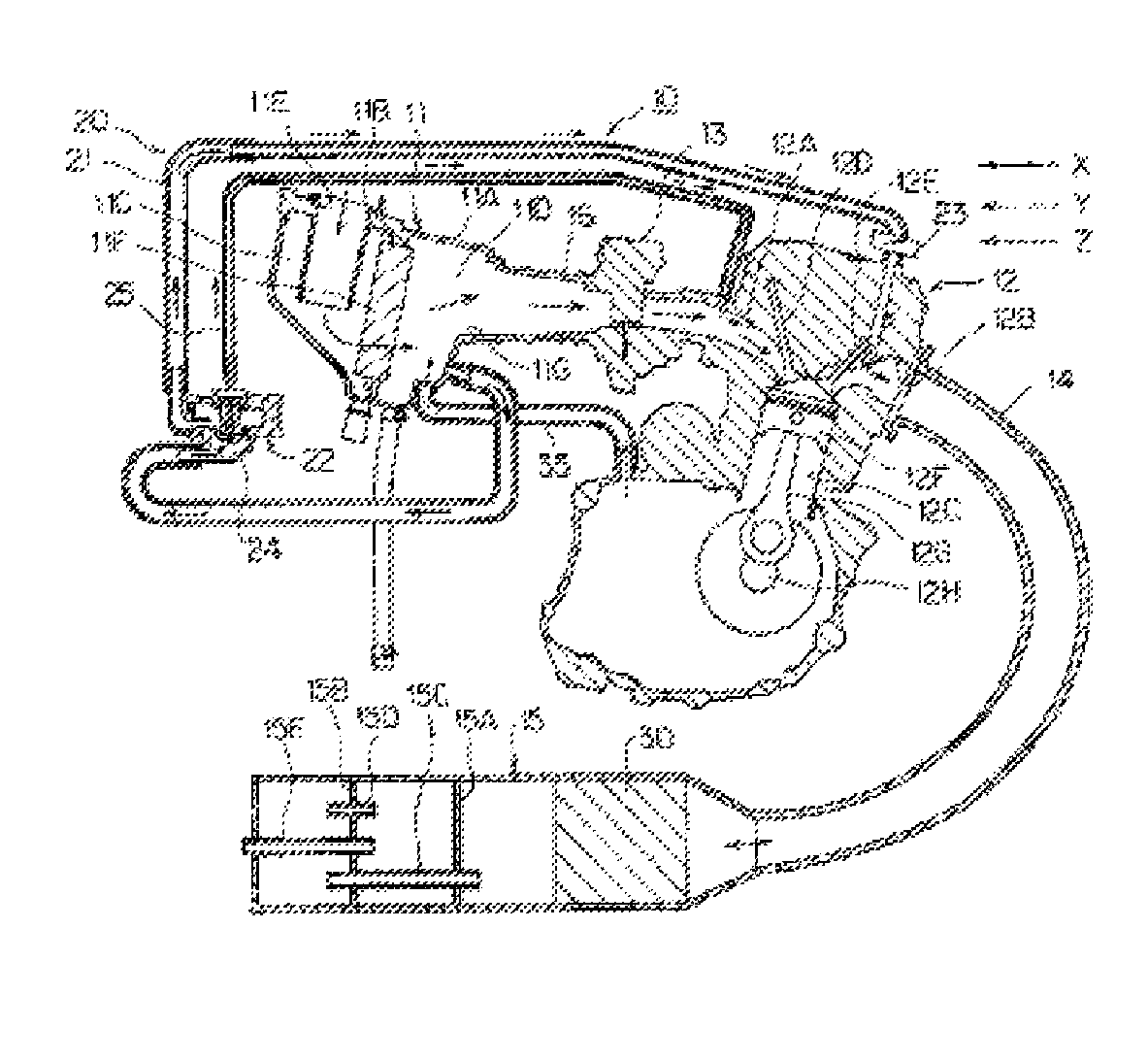
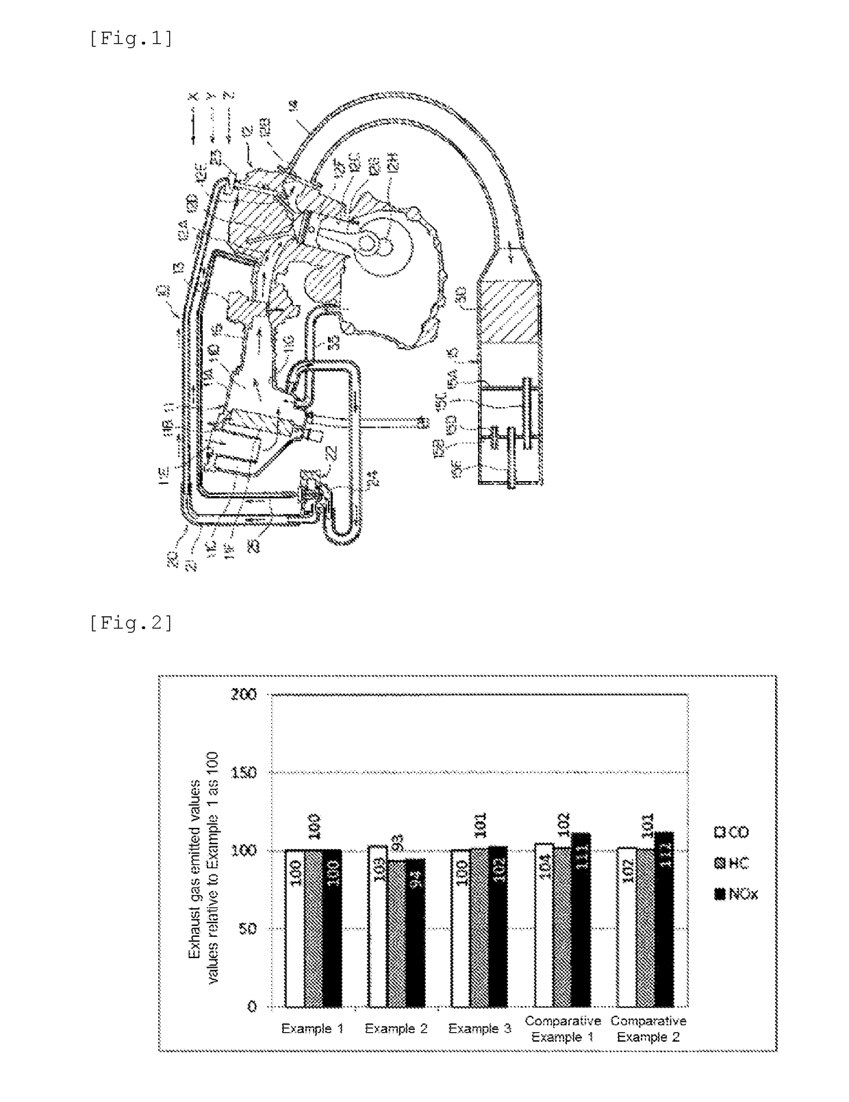

Image

  • Exhaust gas purifying catalyst
  • Exhaust gas purifying catalyst

Examples


example 1

[0161]A ceria-zirconia composite oxide B10 (D50: 6.5 μm, pore diameter: 66 nm, BET specific surface area: 38 m2 / g), an alumina A4 (D50: 13 μm, pore diameter: 22 nm, BET specific surface area: 105 m2 / g), and an alumina sol as an inorganic binder were prepared respectively.

[0162]With regard to a substrate, a metal honeycomb carrier made of stainless steel (300 cells, ϕ30 mm×L30 mm, 21 cc of test pieces volume) was calcined at 500° C. for one hour, thereby oil and dusts attached to the carrier were eliminated.

[0163]A Pd nitrate solution was added with pure water, and 65 parts by mass of the alumina A4 was added thereto, and was then stirred for two hours. Thereafter, 16 parts by mass of the ceria-zirconia composite oxide B10 and 12 parts by mass of the binder material were added thereto, thereby obtaining a first catalyst layer Pd-containing slurry (Pd: 1.6 parts by mass).

[0164]Meanwhile, a Rh nitrate solution was added with pure water, and 70 parts by mass of the ceria-zirconia compos...

example 2

[0168]A catalyst (sample) was produced in the same manner as in Example 1 except that the blending amount of the alumina A4 in the first catalyst layer Pd-containing slurry was changed to 70 parts by mass, and the blending amount of the ceria-zirconia composite oxide B10 was changed to 11 parts by mass in Example 1.

example 3

[0169]A catalyst (sample) was produced in the same manner as in Example 1 except that the blending amount of the ceria-zirconia composite oxide B10 in the second catalyst layer Rh-containing slurry was changed to 90 parts by mass, and the blending amount of the alumina A4 was changed to 0 part by mass in Example 1.


PUM

PropertyMeasurementUnit
particle sizeaaaaaaaaaa
void volume diameteraaaaaaaaaa

Abstract

To reduce an OSC material, while maintaining necessary OSC capacity; and to improve heat resistance and reactivity of a precious metal. Proposed is an exhaust gas purifying catalyst which comprises a first catalyst layer that is formed on the surface of a substrate that is formed of a ceramic or a metal, and a second catalyst layer that is formed on the upper side of the first catalyst layer. The first catalyst layer comprises a precious metal, an OSC material and an alumina, and the OSC material and the alumina are comprised at a mass ratio of OSC material:alumina=1:7 to 1:3. The second catalyst layer comprises a precious metal, an OSC material and an alumina, and the OSC material and the alumina are comprised at a mass ratio of OSC material:alumina=1:1 to 10:0.

Description

TECHNICAL FIELD[0001]The present invention relates to an exhaust gas purifying catalyst which can be suitably used for purifying an exhaust gas emitted from an internal-combustion engine of four-wheel or two-wheel automobiles or the like.BACKGROUND ART[0002]Exhaust gases to be emitted from an internal-combustion engine using gasoline as a fuel include harmful components such as total hydrocarbons (THC), carbon monoxide (CO), and nitrogen oxides (NOx). As such, it is necessary to purify each of the harmful components using a catalyst in such a manner that the total hydrocarbons (THC) are converted into water and carbon dioxide by oxidation, the carbon monoxide (CO) is converted into carbon dioxide by oxidation, and the nitrogen oxides (NOx) are converted into nitrogen by reduction.[0003]As such a catalyst for treating exhaust gas (hereinafter, referred to as “exhaust gas purifying catalyst”), three way catalysts (TWCs) capable of oxidizing and reducing CO, THC and NOx have been used....

Claims


Application Information

Patent Timeline
Patent Type & Authority Patents(United States)
IPC IPC(8): B01J23/63B01J35/02B01J35/04B01D53/94F01N3/10
CPCB01J23/63B01D53/945B01D53/9454B01J35/023B01J35/04F01N3/101F01N2370/02B01D2255/1023B01D2255/1025B01D2255/908B01D2255/9022B01D2255/9202B01D2255/1021F01N3/28B01D53/9468B01D2255/2065B01D2255/20715B01D2255/2092B01D2255/407B01J37/0225B01J37/0244B01J35/0006B01J35/1061B01J35/1066B01J35/109B01J35/0073Y02T10/12
Inventor KIMURA, TOSHIAKIHORIMURA, HIROYUKIYAMAGUCHI, TAKUMIENDO, TAKESHIIIMURO, AKIHIROOSHIMA, RYOICHIHOUSHITO, OHKINAKAHARA, YUNOSUKE
Owner HONDA MOTOR CO LTD
Learn More