
Electric charging device, electric connection device, system and method for charging a battery of a vehicle

a technology for charging devices and batteries, applied in the direction of charging stations, coupling device connections, transportation and packaging, etc., can solve problems such as unsatisfactory uniformity, and achieve the effect of easy control

Active Publication Date: 2018-07-10
ROBERT BOSCH GMBH
View PDF20 Cites 11 Cited by
  • Summary
  • Abstract
  • Description
  • Claims
  • Application Information

AI Technical Summary

Benefits of technology

This patent describes an electric charging device for vehicles that is simple, reliable, and easy to control. The device uses a single actuator to move a part of the lifting device, which in turn moves the charging device. This design prevents interference with other parts of the vehicle and allows for flexibility in vehicle design. The charging head is pressure-controlled to ensure stable contact with the vehicle's surface. The actuator and lifting device are straightforward in construction, making the device easy to modify and improve. Overall, this patent presents a practical solution for charging electric vehicles.

Problems solved by technology

The positioning of the vehicle with respect to the charging device as automatically as possible and the connection of the charging device to the vehicle as automatically as possible for the purpose of charging the battery comprise some technical challenges.
In addition, no uniformity is ensured as a result of a receiving head being arranged on the underbody of the vehicle since vehicles have different heights and the underbody of vehicles is therefore at a different height from a base on which the vehicle stands.

Method used


Image

  • Electric charging device, electric connection device, system and method for charging a battery of a vehicle
  • Electric charging device, electric connection device, system and method for charging a battery of a vehicle
  • Electric charging device, electric connection device, system and method for charging a battery of a vehicle

Examples


first embodiment

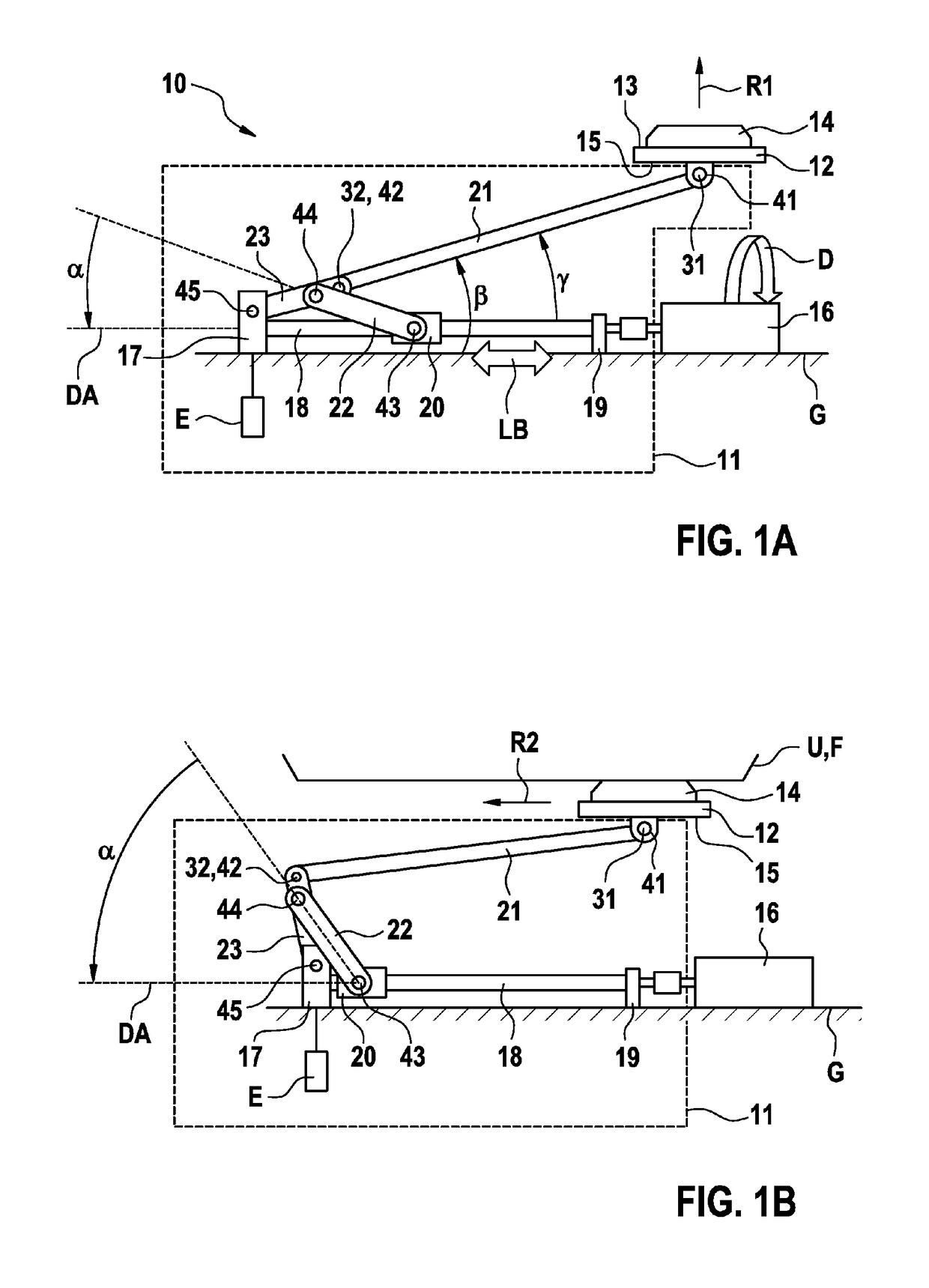
[0041]FIG. 1A shows a schematic side view of an electric charging device 10 for charging a battery of a vehicle according to a first aspect of the present invention in a first state.

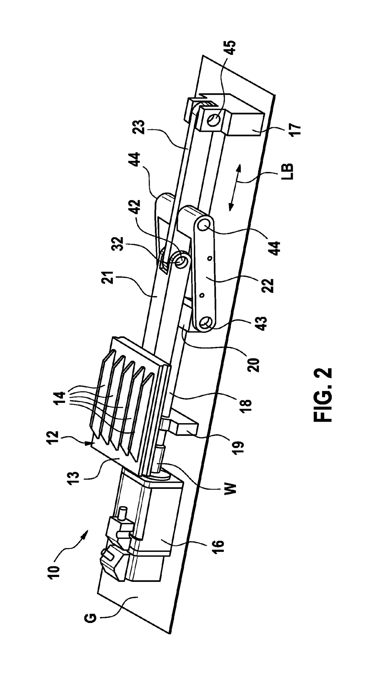
[0042]A charging head 12 has a first plurality of electric contacts 14 at a first surface 13 of the charging head 12. The electric contacts 14 are in the form of lamellae which are parallel to one another and are perpendicular to the first surface 13. When seen from the side, the lamellae are trapezoidal strips, the longer of the two parallel sides of the trapeze respectively being connected to the first surface 13. The charging device 10 is set up on a base G, for example the ground, a floor, a vehicle floor or another suitable flat surface. It is advantageous to fit the charging device 10 on a surface which is lower than the ground and is parallel to the latter or in a recess, for instance in the ground of a parking lot. If the charging device 10 is formed in a compartment or a hollow in a bump, which ...

second embodiment

[0082]FIG. 7 shows a charging head 12′ of an electric charging device for charging a battery of the vehicle according to the first aspect of the present invention.

[0083]The charging head 12′ according to the second embodiment is a variant of the charging head 12 according to the first embodiment, three first electric contacts 14-1, 14-2, 14-3, or 14-i for short, being formed on the first surface 13. A conductive torus is formed on the first surface 13 for this purpose and is divided, by means of two electrically insulating insulation blocks 51, 52, into two regions which are electrically separate from one another and each of which constitutes an individual first contact 14-1, 14-2. A further first contact 14-3 is in the form of an arc between the insulation blocks 51, 52 and is electrically contact-connected via connections inside the insulation blocks 51, 52.

[0084]FIG. 8 shows an electric connection device 110′ of a vehicle for charging a battery of the vehicle according to a secon...


PUM


Abstract

The invention relates to an electric charging device, to a charging system, to a method for charging a battery of a vehicle, and to an electric connection device of a vehicle for charging a battery of the vehicle. The electric charging device comprises the following: a lifting device (11) to which a charging head (12) is coupled, wherein the charging head (12) has a first plurality of first electric contacts (14) on a first surface (13) of the charging head (12), at least some of said contacts being connectable to an energy source in order to charge the battery; and an actuator (16) by means of which the lifting device (11) can be actuated such that the charging head (12) can be at least partly moved in a first direction (R1) that is substantially perpendicular to the first surface (13). The lifting device (11) is further designed such that the charging head (12) can be moved in a second direction (R2) along a stop surface (U, P) by continuing to actuate the lifting device (11) by means of the actuator (16) upon striking the stop surface (U, P) in the first direction (R1).

Description

BACKGROUND OF THE INVENTION[0001]The present invention relates to an electric charging device for charging a battery of a vehicle, to an electric connection device of a vehicle for charging a battery of the vehicle, to a system for charging a battery of a vehicle and to a method for charging a battery of a vehicle.[0002]Hybrid and electric vehicles at least partially resort to batteries in order to supply their drive train with energy. If the battery of a vehicle is empty, it can be recharged at a charging station by means of a charging device.[0003]The positioning of the vehicle with respect to the charging device as automatically as possible and the connection of the charging device to the vehicle as automatically as possible for the purpose of charging the battery comprise some technical challenges. Automated conductive charging systems require precise guidance of a charging head, for example a connector, of the charging device to a receiving head, for example a connector socket,...

Claims


Application Information

Patent Timeline
Patent Type & Authority Patents(United States)
IPC IPC(8): H01R33/00H01R13/631B60L11/18
CPCB60L11/1818B60L11/1824B60L11/1827B60L11/1833H01R13/6315Y02T90/14H01R2201/26Y02T10/7005Y02T10/7088Y02T90/121Y02T90/125B60L2230/12B60L53/16B60L53/30B60L53/35B60L53/36B60L53/18Y02T10/7072Y02T90/12Y02T10/70
Inventor KUFNER, ANNIKA CAROLINKILIC, AHMETSENGEBUSCH, FALCO
Owner ROBERT BOSCH GMBH
Learn More