
Fluidic connector for irrigation and aspiration of wounds

a technology of fluid connectors and wounds, applied in the field of fluid connectors for irrigation and wound aspiration, can solve the problems of affecting the healing process, and damage to the wound site, and achieves the effects of improving fluid connectors, enhancing flexibility, and being more rigid

Active Publication Date: 2018-07-03
SMITH & NEPHEW PLC
View PDF473 Cites 1 Cited by
  • Summary
  • Abstract
  • Description
  • Claims
  • Application Information

AI Technical Summary

Benefits of technology

[0007]Certain embodiments disclosed herein relate to improved fluidic connectors for providing aspiration and irrigation and having enhanced flexibility. Such fluidic connectors may have advantages over prior art dressings which may be more rigid and therefore uncomfortable for a patient, particularly when inserted into or located around sensitive wound areas. Other advantages may be that the fluidic connectors described herein are less prone to obstruction than the more rigid conduits of the prior art. Also disclosed are improved methods of use and systems for use of the same, preferably in conjunction with negative pressure wound therapy.

Problems solved by technology

Whilst such treatment methods work well in practice, the stiffness of the aspiration and irrigation conduits in such close proximity to the wound site can adversely affect the healing process.
Such force can cause disturbance of a wound bed which can damage a wound site.
This can potentially cause delays in healing of the wound site.
These conduits can also cause discomfort to the patient.
The ability to create a fluid tight seal about the area where the conduits pass through the wound dressing can also be challenging.
The conduits may become obstructed by movement of the patient, which may cause part of the tube to bend and form a kink or may place pressure onto the tubing, substantially or fully blocking the flow of fluid through the tubing.
In embodiments employing a separate canister for fluid collection, obstruction of the aspirant conduit can also result in accumulation of excess wound exudate at the wound site.

Method used


Image

  • Fluidic connector for irrigation and aspiration of wounds
  • Fluidic connector for irrigation and aspiration of wounds
  • Fluidic connector for irrigation and aspiration of wounds

Examples


Embodiment Construction

[0078]Preferred embodiments disclosed herein relate to wound therapy for a human or animal body. Therefore, any reference to a wound herein can refer to a wound on a human or animal body, and any reference to a body herein can refer to a human or animal body. The term “wound” as used herein, in addition to having its broad ordinary meaning, includes any body part of a patient that may be treated using negative pressure. Wounds include, but are not limited to, open wounds, incisions, lacerations, abrasions, contusions, burns, diabetic ulcers, pressure ulcers, stoma, surgical wounds, trauma and venous ulcers or the like. Treatment of such wounds can be performed using negative pressure wound therapy, wherein a reduced or negative pressure can be applied to the wound to facilitate and promote healing of the wound. It will also be appreciated that the negative pressure systems and methods as disclosed herein may be applied to other parts of the body, and are not necessarily limited to t...


PUM


Abstract

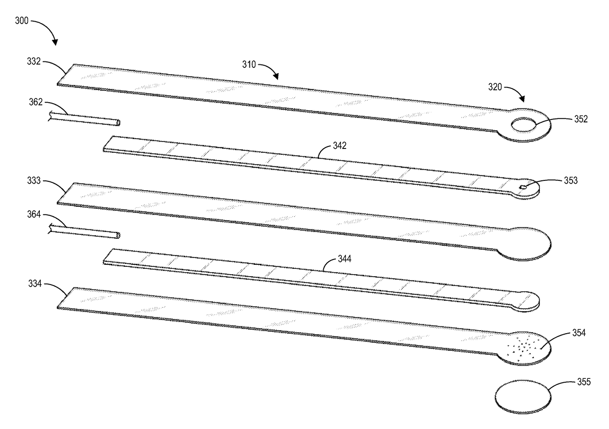
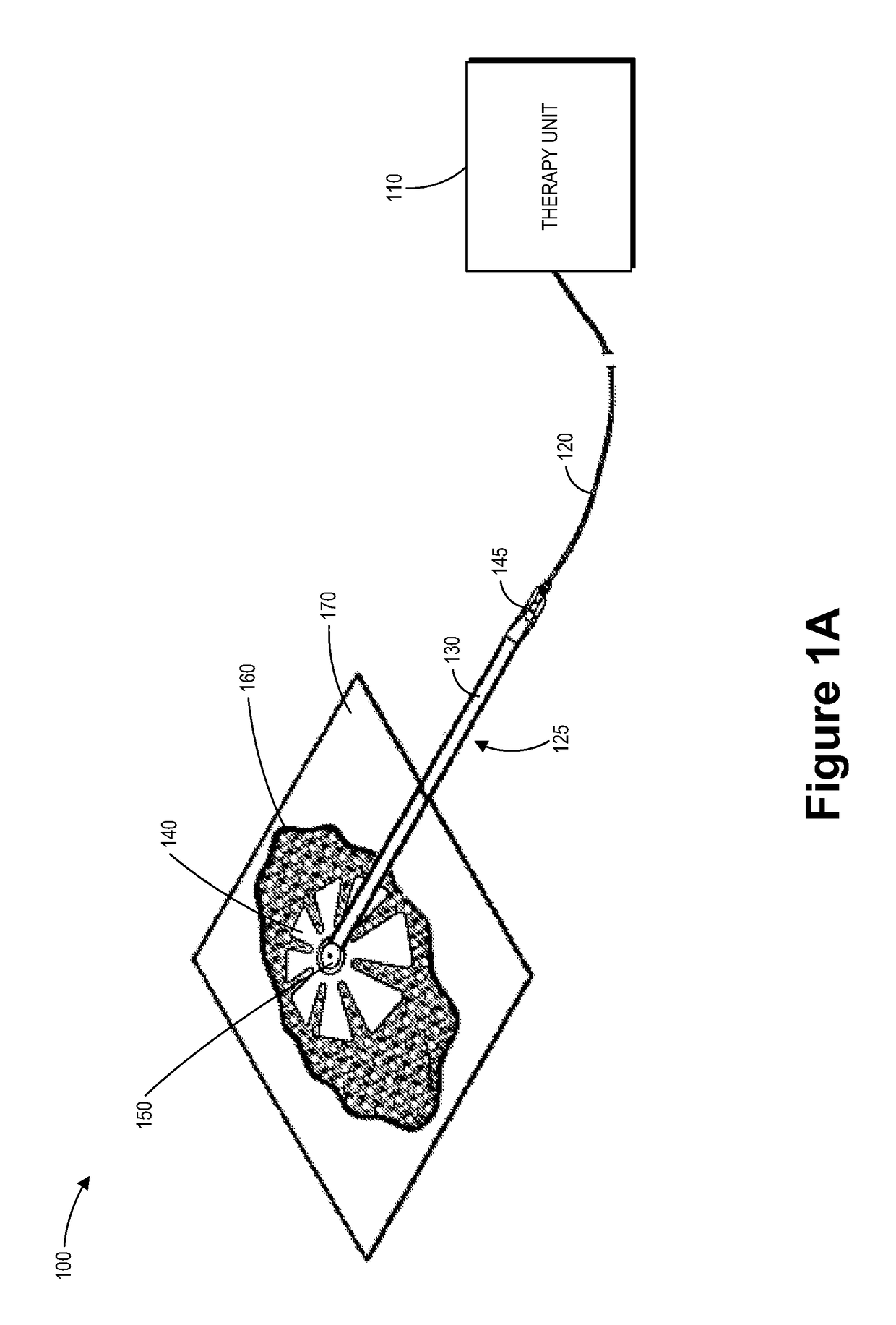
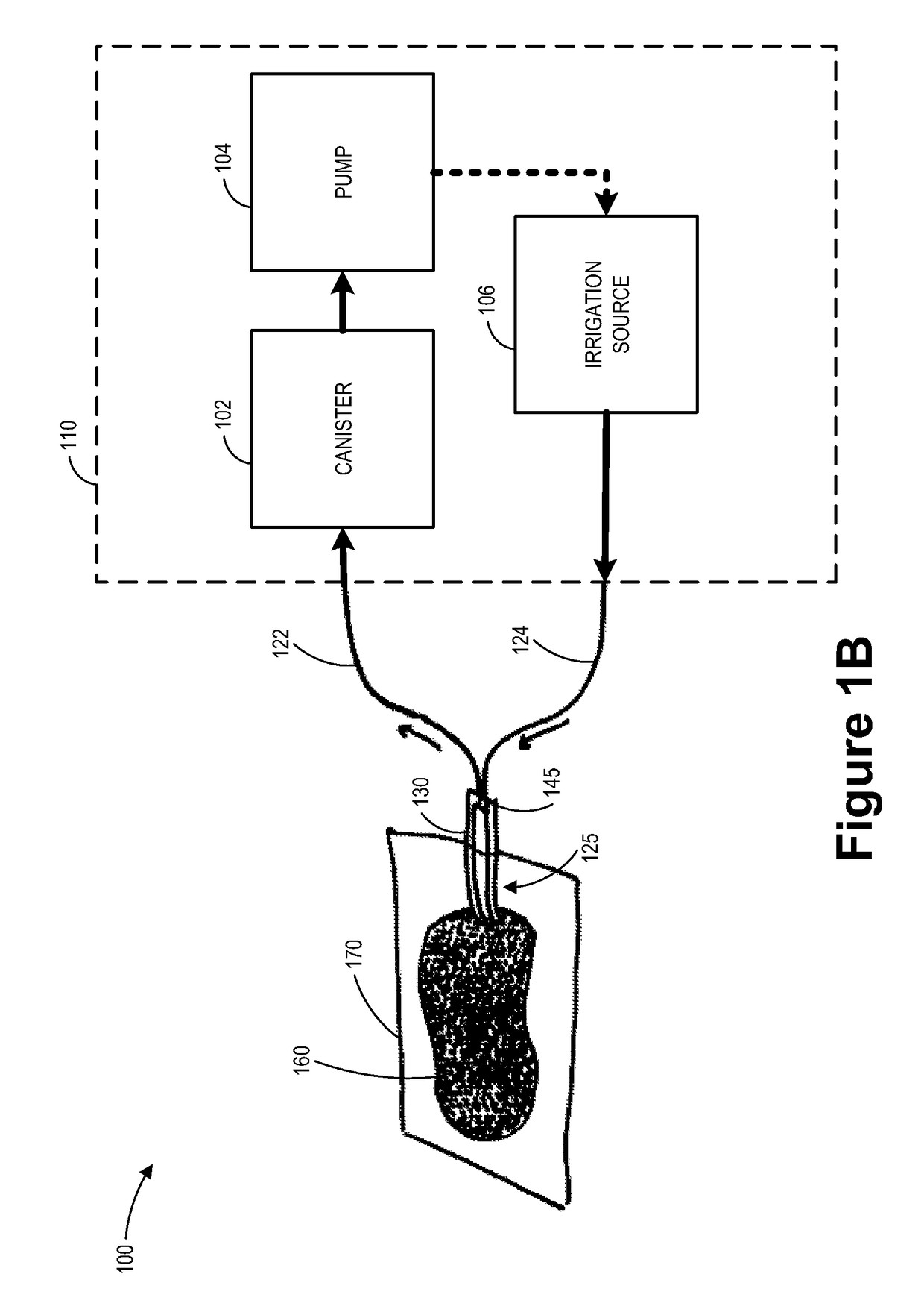
Disclosed herein are several embodiments of a negative pressure apparatus and methods of using the same in the treatment of wounds. Some embodiments are directed towards improved fluidic connectors configured to transmit irrigation fluid and to apply aspiration to a wound, for example using softer, kink-free conformable layers. Some embodiments may comprise a first channel for delivering irrigation fluid to the wound and a second channel for transmitting negative pressure and removing fluid comprising irrigation fluid and wound exudate from the wound, wherein the channels comprise a flexible spacer material. Some embodiments are directed toward an irrigation manifold attachable to or incorporated as part of a distal end of an irrigation and aspiration fluidic connector.

Description

CROSS-REFERENCE TO RELATED APPLICATION[0001]This application is a national stage application of International Patent Application No. PCT / IB2014 / 001682, filed on May 6, 2014, which claims the benefit of U.S. Provisional Application Ser. No. 61 / 822,254, filed May 10, 2013, the entirety of which is hereby incorporated by reference.BACKGROUNDField of the Invention[0002]Embodiments described herein relate to apparatuses, systems, and methods the treatment of wounds, for example by applying irrigation and aspiration to a wound via a fluidic connector.Description of the Related Art[0003]The treatment of open or chronic wounds that are too large to spontaneously close or otherwise fail to heal by means of applying negative pressure to the site of the wound is well known in the art. Negative pressure wound therapy (NPWT) systems currently known in the art commonly involve placing a cover that is impermeable or semi-permeable to fluids over the wound, using various means to seal the cover to ...

Claims


Application Information

Patent Timeline
Patent Type & Authority Patents(United States)
IPC IPC(8): A61M1/00A61F13/00A61F5/00A61M39/10A61M3/02
CPCA61M1/0086A61F13/00068A61M39/105A61M1/0088A61M3/0279A61M1/0084A61P17/02A61M1/85A61M1/912A61M1/94A61M1/913A61M1/90A61M1/86
Inventor HARTWELL, EDWARD YERBURY
Owner SMITH & NEPHEW PLC
Learn More